Warning, Figure 4-1, Figure 4-2 – Scag Power Equipment GC-STC-CS User Manual
Page 8: Figure 4-3
6
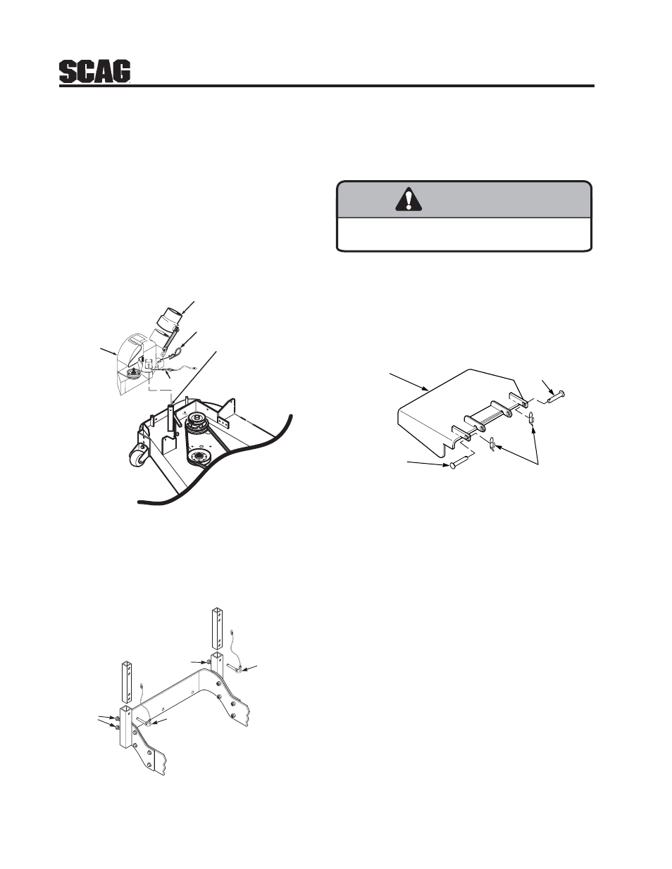
1. Prepare the work area making sure that it is a
clean, safe environment.
2. Remove the rubber strap holding the adapter to
the blower assembly. See Figure 4-1.
3. Remove the pin and hair pin holding the blower
assembly to the mounting bracket on the cutter
deck and remove the blower assembly. See
Figure 4-1.
FIGURE 4-1
4. Loosen the four (4) locking bolts and jam nuts.
Remove the two (2) pins holding the hopper
assembly to the mounting posts on the rear of the
machine. See Figure 4-2.
FIGURE 4-2
4.1 GRASS CATCHER REMOVAL
INSTRUCTIONS
5. With help from an assistant, remove the hopper
assembly from the mounting posts.
6. Re-install the side discharge chute to the opening
on the cutter deck. Replace the two outside
mounting bolts on the discharge chute with the
clevis pins (p/n 04064-15) and rue cotter pins
(p/n 04069-03). See Figure 4-3.
FIGURE 4-3
CLEVIS PIN
P/N 04064-15
CLEVIS PIN
P/N 04064-15
RUE COTTER PIN
P/N 04069-03
DISCHARGE
CHUTE
GC-STC removal art 3
WARNING
WARNING
DO NOT OPERATE WITHOUT DISCHARGE CHUTE, MULCHING
KIT, OR ENTIRE GRASS CATCHER INSTALLED
BLOWER
ASSEMBLY
MOUNTING
BRACKET
PIN
ADAPTER
RIGHT SIDE OF
CUTTER DECK SHOWN
(Note: Some parts not shown for viewing purposes.)
2004 GC-STC removal art 1
HAIR
PIN
2005 GC-STC removal art 2-A
Loosen
Locking
Bolts
Remove
Mounting
Pins
Remove
Mounting
Pins
Loosen
Locking
Bolts