Figure 3-4, Figure 3-5, Figure 3-6 – Scag Power Equipment GC-STC-CS User Manual
Page 7
5
10. Install the new belt covers and secure. See
items number 1 and number 21 on page 10 of the
Blower Mounting Components section in the
Illustrated Parts List for proper installation.
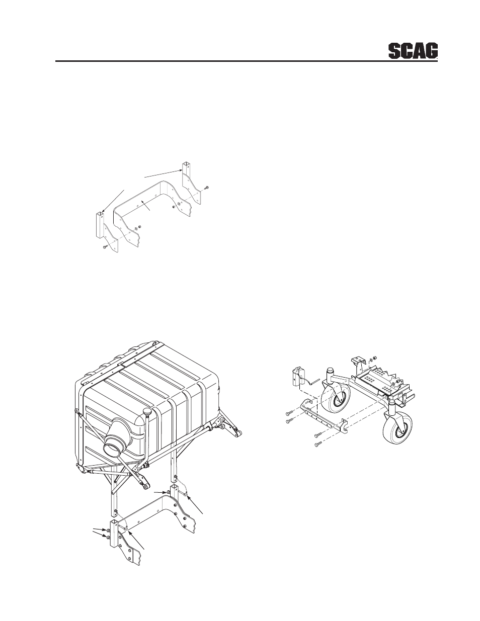
11. Install the hopper mounting brackets to the
outside of the frame on the rear of the machine.
See Figure 3-4.
FIGURE 3-4
12. With help from an assistant, install the hopper
assembly to the machine by installing the
mounting post into the hopper mounting brackets
and secure with the ring pins. Tighten the bolts
and jam nuts. See Figure 3-5.
FIGURE 3-5
-NOTE-
The hopper dump handle can be installed on
either side for operator convenience. When
installing this grass catcher on a machine
with the Roll Over Protection System (ROPS),
the curved handle will need to be installed on
the right side.
13. Install the hose from the blower assembly
adapter to the hopper hood and secure using the
6-1/2" clamps.
14. Using the weight support bar as a guide, identify
the four corresponding mounting holes, and the
existing hardware that will need to be removed
in order to secure the weight support bar to the
front of the machine as shown. See Figure 3-6.
15. Install one 7/16-14 x 1-3/4" hex head bolt into
each of the four mounting holes in the weight
support bar, and through the matching holes in
the caster support weldment. Secure this
assembly to the front of the machine using the
7/16- .5" x 1-1/4" x .083" flatwashers, and the
7/16-14 elastic stop nuts. Torque hardware to
59 ft. lbs. See Figure 3-6.
Figure 4 A GC-STT Install Art
Hopper
Mounting
Brackets
Rear Frame
FIGURE 3-6
16. Operate and test.
Locking
Bolts
Locking
Bolts
Ring Pins
Ring Pins