Chapter 2: installation, X8st3-f/x8ste, Channel 1 slots – SUPER MICRO Computer X8STE User Manual
Page 33: Channel 2 slots channel 3 slots
Chapter 2: Installation
2-9
Possible System Memory Allocation & Availability
System Device
Size
Physical Memory
Remaining (-Available)
(4 GB Total System Memory)
Firmware Hub flash memory (System BIOS)
1 MB
3.99 GB
Local APIC
4 KB
3.99 GB
Area Reserved for the chipset
2 MB
3.99 GB
I/O APIC (4 Kbytes)
4 KB
3.99 GB
PCI Enumeration Area 1
256 MB
3.76 GB
PCI Express (256 MB)
256 MB
3.51 GB
PCI Enumeration Area 2 (if needed) -Aligned on
256-MB boundary-
512 MB
3.01 GB
VGA Memory
16 MB
2.85 GB
TSEG
1 MB
2.84 GB
Memory available for the OS & other applications
2.84 GB
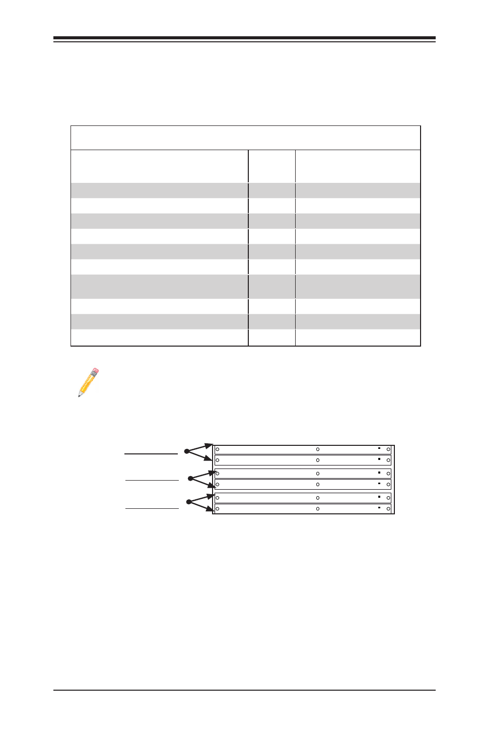
Note : The motherboard will NOT boot if DIMM module(s) are installed
in any of the Bank2 slots but none in the Bank1 slots. The first DIMM
module must be installed in DIMM1A, and all Bank1 slots must be filled
before populating any Bank2 slot(s).
Channel 1 Slots
BMC JTAG
1
SAS1
SAS2
SAS7
SAS3
SAS4
SAS5
SAS6
JWOL
Battery
JD1
SPKR1
JAR
JI2C1
JI2C2
JPS2
JL1
1
JOH
1
JF1
LES1
LE1
COM1
FAN4
FAN3
FAN5
FAN2
FAN1
JPW1
SMBUS_PS1
JPW2
JPG1
JPUSB3
JBMC1
JPS1
JPUSB2
JPL1
JPL2
JLED
JWD
JPUSB1
IPMI_LAN
COM2
Floppy
I-Button
T-SGPIO1
3-SGPIO2
3-SGPIO1
USB 6/7
USB 4/5
USB3
USB2
Slot6 PCI-E 2.0 X8 on X16
Slot3 PCI-E 2.0 X8
I-SA
TA4
I-SA
TA5
Slot4 PCI-E 2.0 X4 on X8
Slot2 PCI 33MHz
Slot5 PCI-E 2.0 X8
I-SA
TA2
I-SA
TA3
DIMM1B
DIMM1A
DIMM3B
DIMM2B
DIMM2A
DIMM3A
I-SA
TA0
I-SA
TA1
X8ST3-F/X8STE
USB 0/1
LAN2
LAN1
VGA
KB/MOUSE
BIOS
JBT1
Slot1 PCI 33MHz
SAS0
T-SGPIO2
LAN CTRL
for IPMIl LAN
LAN
CTRL1
LAN
CTRL2
SI/O
BMC CTRL
BMC
Firmware
SAS CTRL
Intel ICH10R
South Bridge
Intel X58-Express
North Bridge
Intel Processor
LES2
LSI 1068E
WPCM 450
CPU FAN
Channel 2 Slots
Channel 3 Slots
Address Extension (PAE) mode behavior which improves driver compat-
ibility. For more information, please read the following article at Microsoft’s
Knowledge Base website at: http://support.microsoft.com/kb/888137.