Gcxee`e^;ifg;fnej, Xczlcxk`e^;lzki\j`jkxez – Woodstock SHOP FOX W1687 User Manual
Page 27
-25-
Df[\cN(-/.=fiDXZ_`e\jD]^%J`eZ\0&((
FG
<
I
8
K@FEJ
GcXee`e^;ifg;fnej
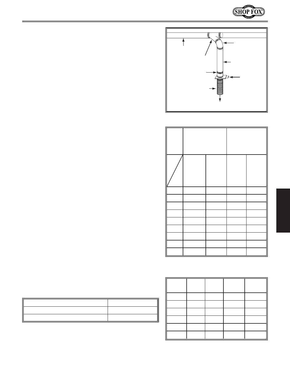
Plan the drop downs for each machine, using blast gates
wherever possible to control airflow.
KfGcXe\i
9cXjk>Xk\
=c\oG`g\
I`^`[G`g\
I`^`[G`g\
DX`eC`e\
:cXdg P9iXeZ_ =`^li\*-% Drop down setup. :XcZlcXk`e^;lZkI\j`jkXeZ\ Adding duct work, elbows, branches and any other To help you think about this resistance, imagine riding a The purpose of calculating the resistance is to determine In most small/medium shops it is only necessary to KfZXcZlcXk\k_\jkXk`Zgi\jjli\f]Xep^`m\ec`e\`ek_\ (% Make a list of each size duct in the line, including the length, and multiply those numbers by the static )% List each type of elbow or branch and multiply the quantity (if more than one) by the static pressure *% Add the additional factors from the table below to your list. ;lZk 8ggifo`dXk\ 8ggifo`dXk\ Main Branch Main Branch 2" .091 .122 .35 .453 2.5" .08 .107 .306 .397 3" .071 .094 .271 .352 4" .057 .075 .215 .28 5" .046 .059 .172 .225 6" .037 .047 .136 .18 7" .029 .036 .106 .141 8" .023 .027 .08 .108 9" .017 .019 .057 .079 =`^li\*/%Lower static pressure loss chart. =`kk`e^ 0'ñ +,ñ +,ñ 0'ñ 3" .47 .235 .282 .188 4" .45 .225 .375 .225 5" .531 .266 .354 .236 6" .564 .282 .329 .235 7" .468 .234 .324 .216 8" .405 .203 .297 .189 =`^li\*.%Upper static pressure loss chart. 8[[`k`feXc=XZkfij JkXk`ZGi\jjli\ Seasoned Dust Collection Filter 5" Entry Loss at Large Machine Hood 2" =`^li\*,%Additional factors affecting static pressure.
components to a duct line increases airflow resistance
(static pressure loss). This resistance can be minimized by
using rigid (smooth) pipe and gradual curves, as opposed
to flexible pipe and 90˚ elbows.
bicycle in a tunnel that is an exact replica of your duct
work. If the inside of the tunnel is very bumpy (flexible
pipe) and has a lot of sharp turns (90˚ elbows), it will take
a lot more effort to travel from one end to the other.
if it is low enough from the machine to the dust collector
to meet the given CFM requirement for the machine. Use
the provided tables to calculate the resistance of duct
work.
calculate the line with the longest duct length or the
most fittings (operating under the assumption that if the
line with the highest resistance works, the others will be
fine).
jpjk\d#[fk_\j\jk\gj1
pressure value given in the upper chart.
loss given in the lower chart.
;`X%
JkXk`ZGi\jjli\
CfjjG\i=ffkf]
I`^`[G`g\
JkXk`ZGi\jjli\
CfjjG\i=ffk
f]=c\oG`g\
Lines
at 3500
FPM
Lines
at
4000
FPM
Lines
at
3500
FPM
Lines
at
4000
FPM
;`X%
Np\P
Np\P