JVC 340 SC User Manual
Page 80
Chapter 2—Functional Descriptions
2-68
Model 330. 340SC, and 370SC Service Manual
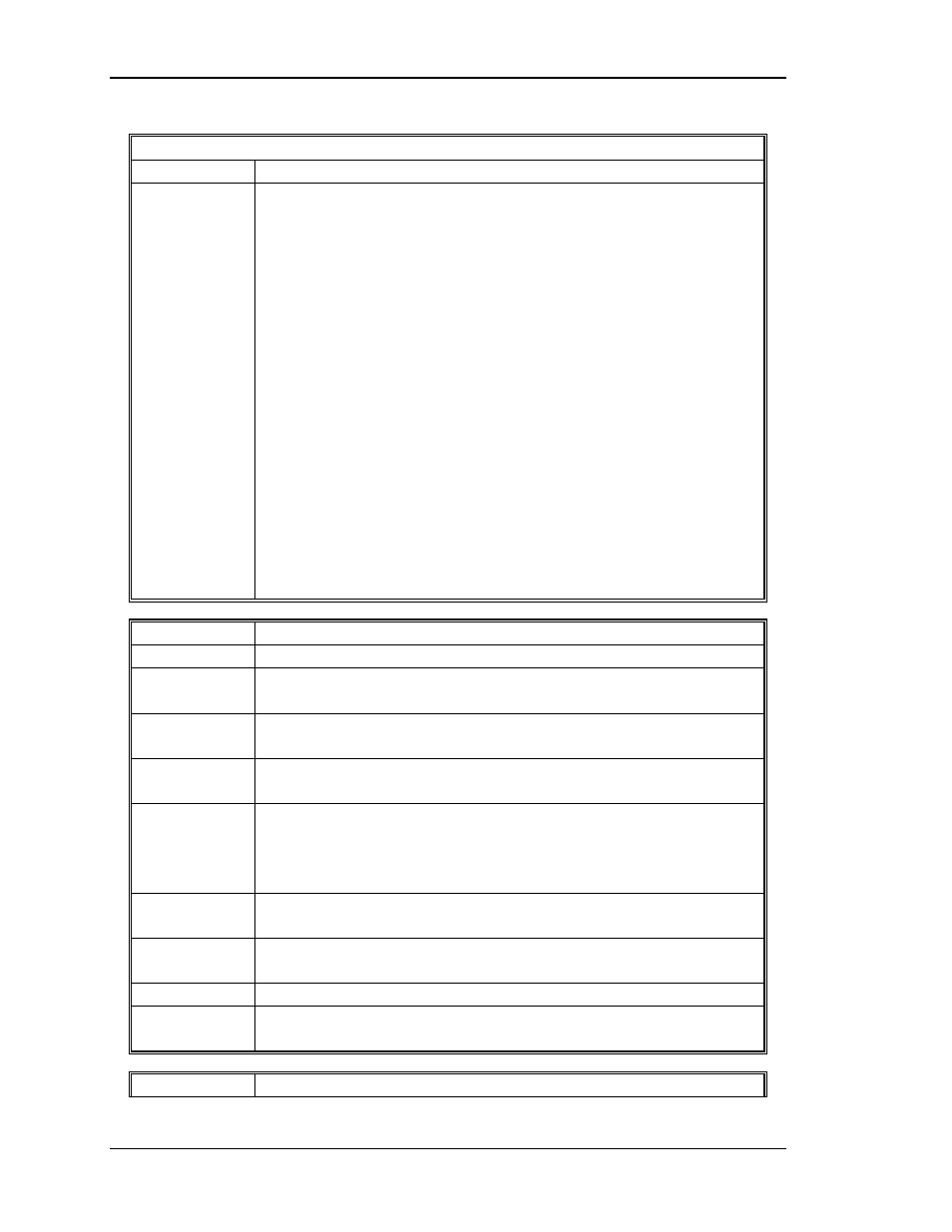
Raster Timing Generator
I/O
Description
IICDATA
Data line for transferring the following data (I = input, 0 =
output). The input data are associated with an interrupt pulse.
O Priority Select
I
/Sync Select
I
Internal Sync
I
Horizontal Count
I
/Phase Lock
I
INTI
O Vertical Flyback Start Delay
O Map Start Delay
O L Blank
O R Blank
O U Blank
O D Blank
O /STBP
O DC Restore Delay
I
Phase Count
I
Correction Delay
I
Pincushion Start Delay
Input
Description
/IICINT
Interrupt used to tell the SCB that the RTG has data to report.
/FRAMEST
Timing pulse Indicating the beginning of a frame. Used in the
SCB for counting vertical frequency. (TP5)
/MAPST
Signal used to start the correction and overlay address counters
during each vertical sweep. (TP12)
/Hx112
Clock pulse at 112 times the horizontal frequency. Used for
convergence and Z-axis correction map generation. (TP20)
/Hx224
Square wave signal 224 times the horizontal frequency for
overlay map generation, horizontal map correction start, left
and right blanking, DC restore, and other timing functions.
(TP23)
/FIELD1
TTL level indicating which field of an interlaced frame (Low if
non-interlaced. (TP8)
/CORRSTRT
Signal used to start the convergence and overlay address
generators during each horizontal sweep. (TP4)
INTI
Indicates when input source signal is interlaced. (TP2)
/VSYNC
Regenerated vertical sync signal, pulse-shaped to 3 horizontal
lines in width. (TP21)
Output
Description