JVC TK-C215V4U User Manual
Page 15
15
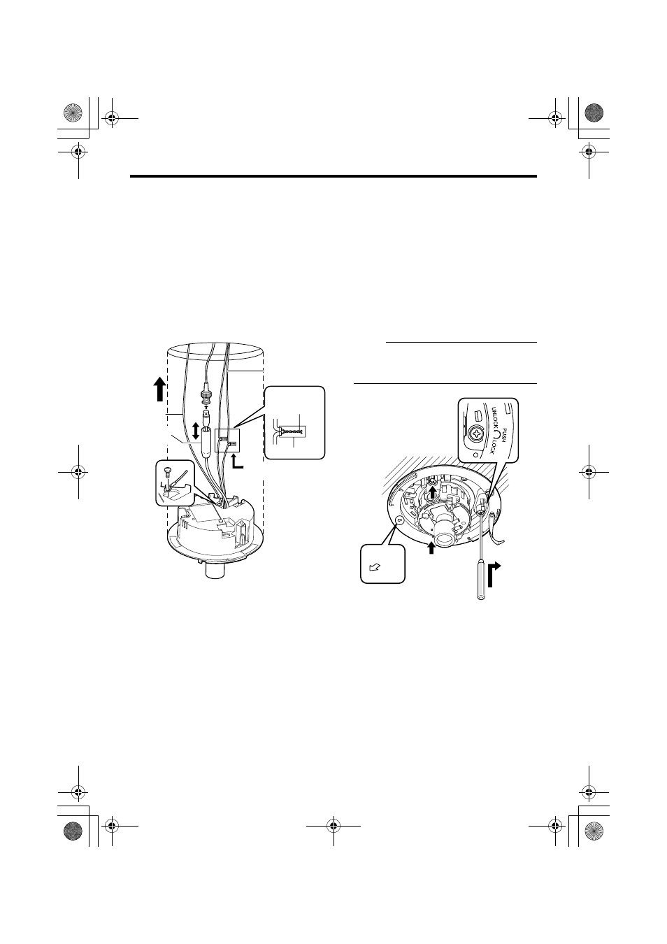
Ⅵ Connecting
1.
Attach the fall prevention wire to the
camera, followed by attaching it to the
ceiling slab (Fall prevention wire is not
included.)
2.
Connect the video signal cable. (
Lower the cover and connect the connectors.
Upon connecting, cover the connectors using
the protection cover.
3.
Connect the input power supply cable.
(
4.
Wrap insulation tape around cables.
5.
Insert the camera unit into the ceiling hole.
Ⅵ Mounting
1.
Align
j with the shooting direction when
mounting the camera.
2.
Fasten the camera. (x3 locations)
A
Press the screw head of the ceiling mount
bracket all the way in using a cross
screwdriver.
B
With the screw pressed in using the
screwdriver, turn about 90
Њ in the clockwise
direction, followed by pulling out the
screwdriver.
C
The ceiling mount bracket is attached to the
ceiling and the camera fastened.
NOTE:
Dismantle the camera upon turning the screw
heads of the ceiling mount bracket (x3) by 90
Њ
in the counterclockwise direction.
Ⅵ Adjusting Images
After mounting is completed, adjust the
images while checking the actual image.
(
1.
5.
2.
4.
3.
Protection
cover
Solder or crimp
Insulation tape
Wrap with tape
Input power
supply cable
Fall prevention
wire
(not supplied)
B
A
1.
2.
FRO
NT
UP
Align with shooting direction
TK-C215V4_EN.book Page 15 Wednesday, June 14, 2006 8:00 PM