System configuration – JVC DY-70E User Manual
Page 7
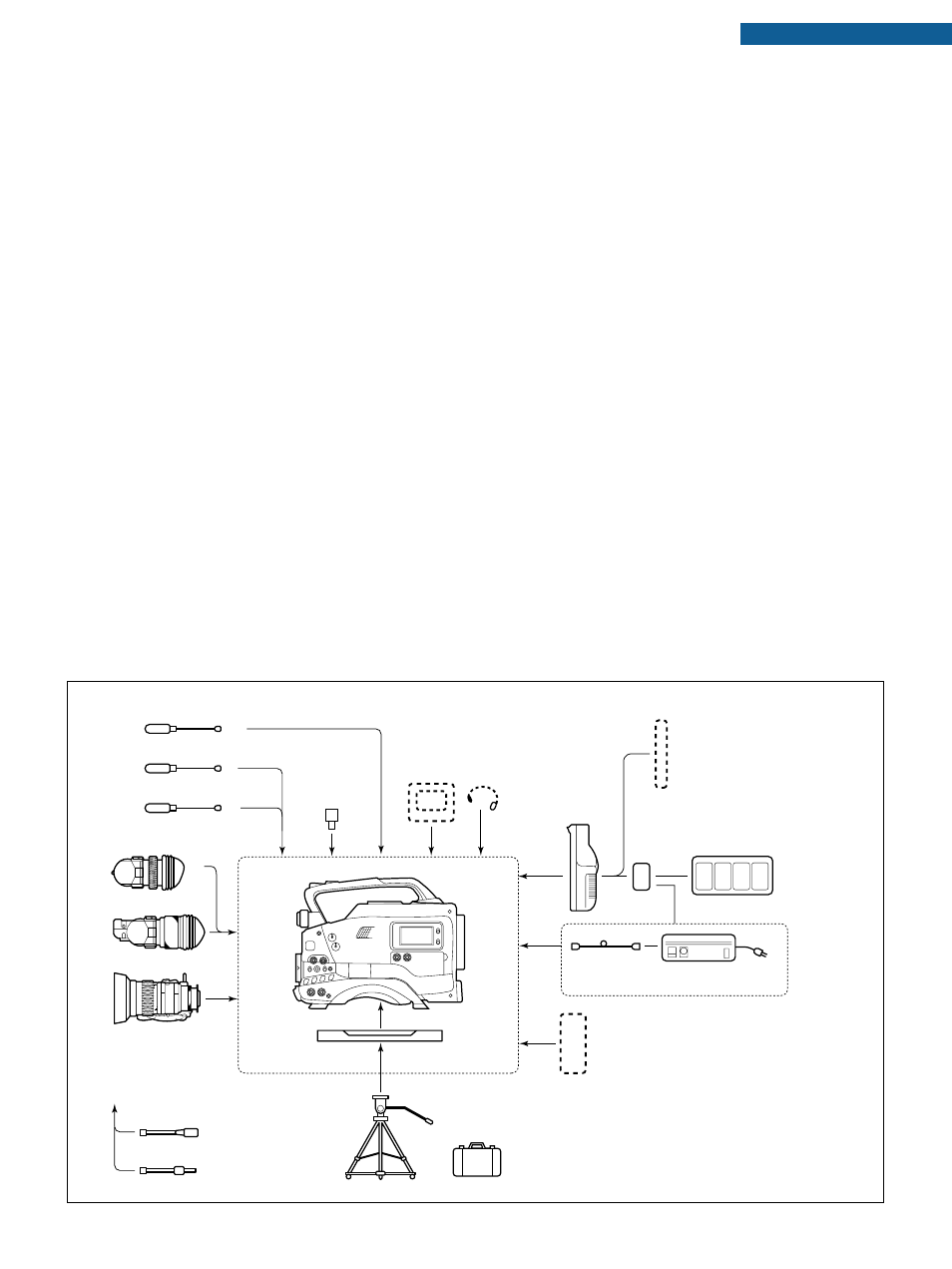
6P
6P
4P
4P
3P
AC
NEW MICROPHONE
MV-P615E
NEW MICROPHONE
MV-P616E
MONO/STEREO MICROPHONE
MV-P612E
1.5" VIEW FINDER
VF-P115E
1.5" VIEW FINDER
VF-P116E
ZOOM LENS
YH14x7.3K12U
YH18x6.7K12U
S14x7.5B12U
S17x6.6BRM
S19x6.5B12U
FOCUS MANUAL UNIT
HZ-FM13U (FUJI)
HZ-FM15U (CANON)
ZOOM SERVO UNIT
HZ-ZS13BU
TRIPOD
TP-P300U
DOLLY
TP-P205U
CARRYING CASE
CB-P90U/CB-27U (U.S.A. only)
TRIPOD BASE
ANTON BAUER BATTERY
(PRO PAC. MAGNUM, TRIMPAC, HYTRON)
VC-710 (5m)
AC POWER ADAPTER
(NB-G1U BATTERY CHARGER)
AA-P250E
NB-G1U (4 PACK) BATTERY CHARGER
(AC POWER ADAPTER)
AA-G10E (B)
BATTERY
NB-G1U
BATTERY
NP-1 TYPE
BATTERY HOLDER
BH-P27U
EARPHONE
MONITOR
MIC HOLDER
KA-A90U
DY-70E
STANDARD PACKAGE
System Configuration
q
Viewfinder mount base, sliding
securing ring
w
[VF] Viewfinder connector
e
[MIC 2 IN + 48 V] Microphone 2
input connector
r
[LENS] control connector
t
[ZEBRA] switch
y
[VTR] trigger button (record start/
stop button)
u
[AUTO WHITE/ACCU FOCUS]
switch
i
Lens mounting ring/Lens lock
lever
o
[FILTER] Colour temperature
conversion filter control knob
!0
[MIC IN 1 IN] Microphone 1 input
connector (6-pin)
!1
Mic holder mounting screw holes
!2
[GEN LOCK IN] connector (BNC)
!3
[TC IN] connector (BNC)
!4
[TC OUT] connector (BNC)
!5
[MONITOR OUTPUT] connector
(BNC)
!6
[CAM/VTR] Monitor output
CAM/VTR switch
!7
Cassette cover
!8
[VTR] trigger button
(record start/stop button)
!9
[POWER] switch
@0
[VTR] switch
@1
[GAIN] switch
@2
[AUTO IRIS] Auto iris level switch
@3
[FULL AUTO] Full auto shooting
on/off button and indicator
@4
[MIC REC LEVEL] control
@5
[MONITOR] Audio monitor
control
@6
[ALARM] control
@7
[OUTPUT] Colour bar/Camera/
Auto knee switch
@8
[W.BAL] White balance switch
@9
[BLACK] Black stretch/black
compression switch
#0
[LOLUX] on/off button
#1
[SHUTTER] switch
#2
[FILE] switch
#3
[MENU] button
#4
[ITEM] button
#5
[UP] button
#6
[SET/DISPLAY] button
#7
[DOWN] button
#8
[PHASE H] Horizontal phase control
#9
[PHASE SC FINE] Colour sub-
carrier phase control
$0
[PHASE SC COARSE] Color
sub-carrier phase coarse
adjustment control
$1
Monitoring Ioudspeaker
$2
Lithium battery installation case
$3
[AUD1 LEVEL] control
$4
[AUD2 LEVEL] control
$5
[MIC1/MIC2] select switch
$6
[MIC2/1L (MONO) auto/manual
select switch
$7
[MIC1R] auto/manual select
switch
$8
[AUD1·2] auto/manual select
switch
$9
[WARNING] indicator
%0
[AUDIO MONITOR] switch
%1
[LIGHT] switch
%2
[COUNTER] switch
%3
[RESET] button
%4
Audio level meters
%5
Warning indicators
%6
MENU indicator
%7
Time code-related indicators
%8
Counter display
%9
Remaining battery power
indicator
^0
Cassette/tape direction/
remaining tape time indicators
^1
[MENU] button
^2
[HOLD/GROUP] button
^3
[SHIFT/ITEM] button
^4
[ADVANCE/SELECT] button
^5
[PRESET/DATA SET] button
^6
[PRESET/REGEN] switch
^7
[REC/FREE] run switch
^8
[TC DISP] switch
^9
Operation cover
&0
[EJECT] button
&1
[PLAY] button
&2
[STOP] button
&3
[REW] button
&4
[FF] button
&5
Back tally lamp
&6
[DC IN] connector (XLR 4-pin)
&7
[DC OUT] connector
&8
[EAR.] earphone jack
&9
[AUD1 IN LINE/MIC] select
switch
*0
[AUD2 IN LINE/MIC] select
switch
*1
[LINE OUT] connector
(XLR 5-pin)
*2
[AUD2 IN] Audio 2 input
connector (XLR 3-pin)
*3
[AUD1 IN] Audio 1 input
connector (XLR 3-pin)
*4
Battery holder
D-9 CAMCORDER DY-70E