Basic connection example – JVC LM-17G User Manual
Page 17
16
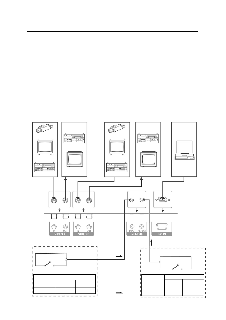
External control switch
External control
functions Open
circuit
(open)
Closed circuit
(short)
INPUT INPUT
A
INPUT
B
REMOTE
(Remote cable)
External control switch
open circuit (open)
RCA pin
closed circuit (short)
REMOTE
(Remote cable)
External control switch
RCA pin
open circuit (open)
closed circuit (short)
Basic Connection Example
Notes:
・
Before connecting your system, make sure that all devices are turned off.
・
The illustration shows some examples of different connections. Terminal connections may differ depending on
the devices. Be sure to refer to the manuals provided with the devices.
・
Each pair of input (IN) and output (OUT) terminals are bridge-connected
・
If you’re not connecting any equipment to a bridged output (OUT) terminal, be sure not to connect any other
cables to the bridged output (OUT) terminal as this will cause the terminating resistance switch to open (auto
terminate function).
・
When making a bridge connection, connect the input (IN) and output (OUT) terminals on the monitor to separate
video components.(For example, if both terminals are connected to the same VCR, resonance may occur except
during playback. This is caused by the same video signal “looping” between the VCRs, and is not a malfunction.)
・
The ASPECT or INPUT A/B settings can be controlled via the ASPECT or INPUT jack in the REMOTE terminal.
・
When using REMOTE terminal, set REMOTE function ON . See “SYSTEM SETTING menu “ on page 11.
Video Camera
Video Monitor
VCR
Video Monitor
VCR
PC
VCR
Video Monitor
Video Monitor
VCR
Video Camera
External control switch
External control
functions
Open circuit
(open)
Closed circuit
(short)
ASPECT
RATIO
4 – 3 (4:3) 16 – 9 (16:9)
Signal Flow