M40e fpcs description – Juniper Networks M40e User Manual
Page 5
•
•
•
•
•
•
•
•
•
•
•
•
•
•
•
•
•
•
•
•
•
•
•
•
•
•
•
•
•
•
•
•
•
•
•
•
•
•
•
•
•
•
•
•
•
•
•
•
•
•
•
•
•
•
•
•
•
•
FPC Installation Instructions
5
FPC Description
M40e FPCs Description
In an M40e router, up to eight FPCs install vertically into the midplane from the front of the
chassis. Each FPC is referenced by the number of the slot in which it is installed. The slot
numbers range from FPC0 through FPC7, from left to right in the chassis.
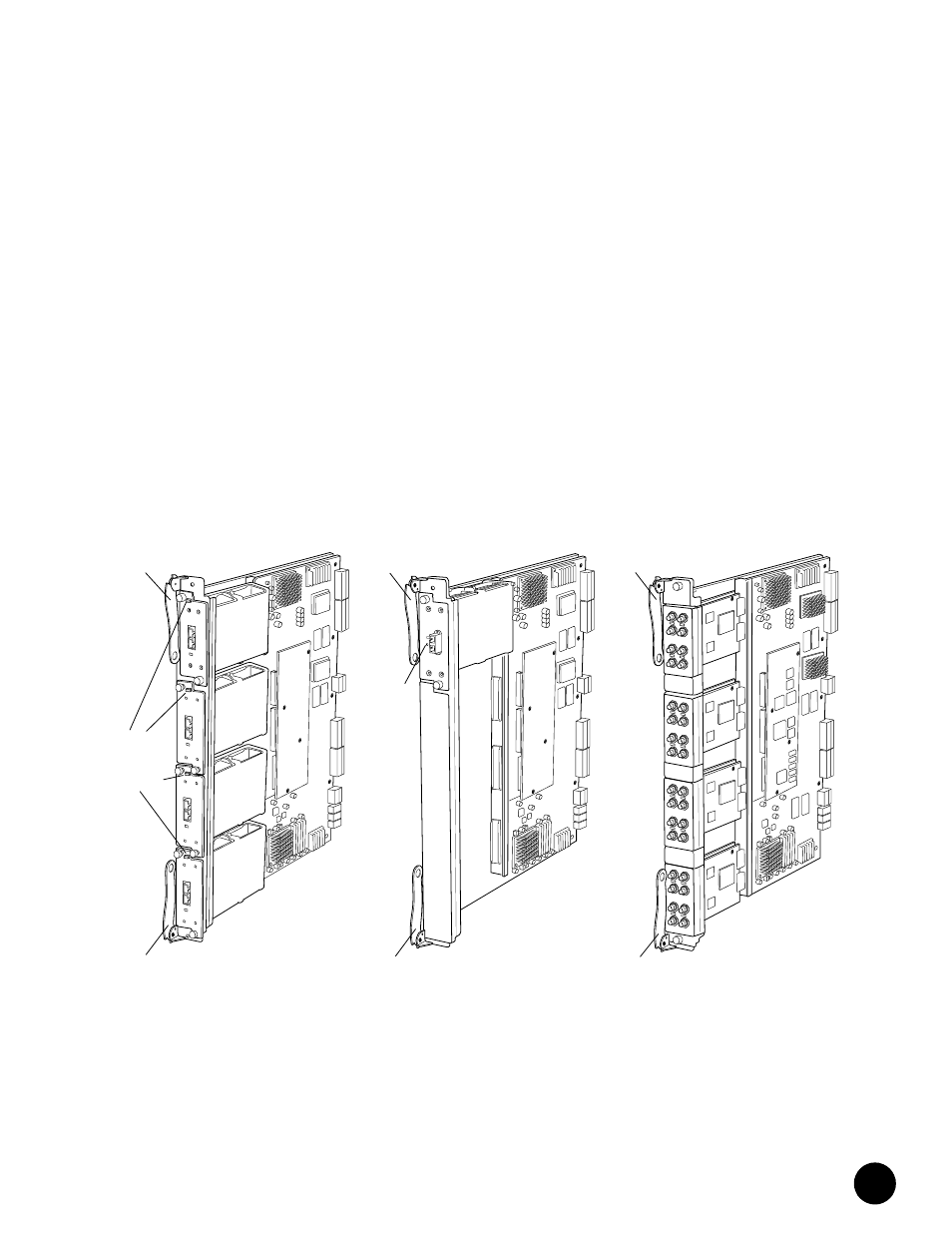
The M40e router supports the three types of FPC shown in Figure 3:
! M40e-FPC—Accommodates up to four PICs of the type also supported on
M20 and M40 routers.
! M40e-FPC1—Accommodates up to four lower-speed PICs such as single-port OC-12 and
Gigabit Ethernet interfaces. The offline button for each PIC is on the FPC card carrier.
! M40e-FPC2—Accommodates one higher-speed PIC, such as an OC-48/STM-16 interface.
The lower three slots in the M40e-FPC2 are covered by a blank panel. The offline button
for the PIC is on the PIC faceplate.
Figure 3: M40e-FPC, M40e-FPC1, and M40e-FPC2
M40e-FPC
Ejector lever
Ejector lever
Ejector lever
M40e - FPC2
Ejector lever
Offline
button
Ejector lever
M40e - FPC1
Ejector lever
Offline
buttons
(on FPC)
1944