Jims USA Twin Cam Racekit Box 1 1208-1351 User Manual
Page 9
555 Dawson Drive, Camarillo, CA 93012 Phone 805-482-6913 • Fax 805-482-7422
8
Rev I
9-12
No.1208-1351
A Division of Thiessen Products, INC
IIn
ns
st
tr
ru
uc
ct
tiio
on
n S
Sh
he
ee
et
t F
Fo
or
r B
Bo
ox
x 1
1 1
12
20
0”
”,, 1
13
31
1”
”,, o
or
r 1
13
35
5”
”
E
En
ng
giin
ne
e A
As
ss
se
em
mb
bl
liie
es
s O
Or
r E
En
ng
giin
ne
e R
Ra
ac
ce
e K
Kiit
ts
s
STEP 5: Oil filter mount installation
•
Remove stickers located over 2 holes located where filter mounts to case.
•
Refer to the instructions included with your oil filter mount kit for
Engine “A” 99-05 FXD, and 99-06 FLH.
•
For Engine “B” and 06-Pres.FXD remove 1-7/8 sticker from case
where filter mounts. Thread in adapter with lock patch into case with
a 7/8” hex socket, torque to 120-168 inch-lbs.
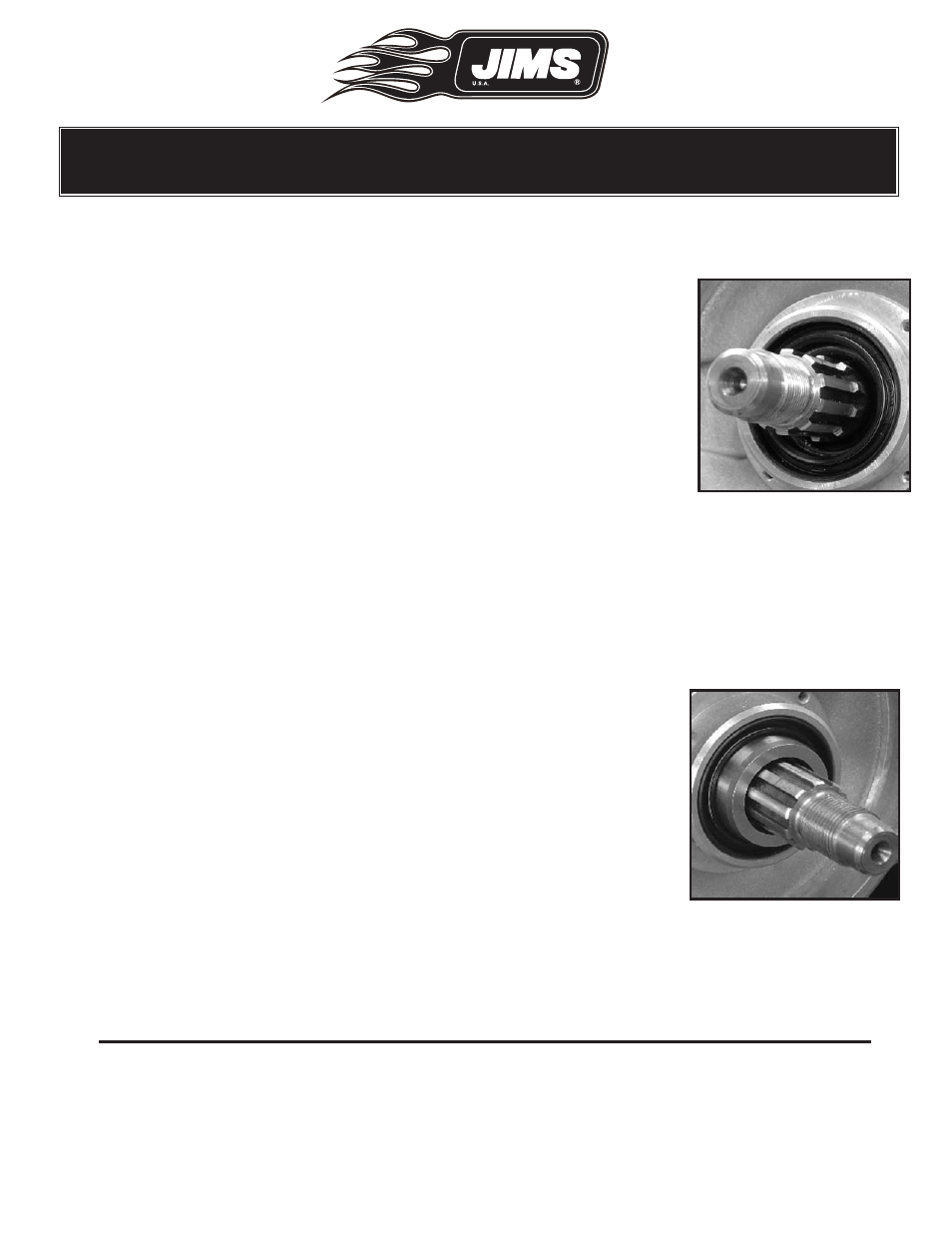
STEP 6: Sprocket shaft spacer installation
•
Inspect the engine sprocket shaft, seal and bearing cavities for any
packaging debris before continuing. See Fig. 14
•
Locate spacer specific to your application:
•
For 1999 to 2005 Dyna "A" use H-D 24038-99A, JIMS No.1286-1319, spacer, .888” long.
•
For 2006 to present Dyna "A" use H-D 24008-99A, JIMS No.1286-1320, spacer, 1.0950" long.
•
For 1999 to present FL "A" use H-D 24008-99A, JIMS No.1286-1320, spacer, 1.0950" long.
•
For 2000 only Softail "B" use H-D 24038-99A, JIMS No.1286-1319, spacer, .888" long.
•
For 2001 to - 2006 Softail "B" use H-D 24039-01A, JIMS No.1486-1834, spacer, .988" long.
•
For 2007 to - present Softail "B" use H-D 24008-99A, JIMS No.1286-1320, spacer, 1.0950" long.
•
Inspect spacer for nicks and dents.
•
Lightly coat outside diameter of sprocket shaft spacer and the inside
of the sprocket shaft seal with clean 20w-50 H-D
®
motor oil.
•
Slide sprocket shaft spacer onto sprocket shaft, (see illustration)
until it is seated on the sprocket shaft bearing. See Fig.15. If you pur-
chased a complete engine assy, go to page 11 step 11 of the Box 3
Instructions #1208-1353.
You now have a completed “Short Block.”
Cover and seal this assembly with the supplied clear plastic bags. When ready
proceed to Box 2 installation instructions.
NOTES
Fig.14- Inspect
Fig.15- Install spacer