3 definition of real-time wait symbols, 4 external bus cycles, real-time wait states, Figure 13. external bus cycle: code fetch/data rea – Intel 8XC251SA User Manual
Page 28: Table 12. real-time wait timing symbol definitions, Preliminary
28
PRELIMINARY
8XC251SA/SB/SP/SQ HIGH-PERFORMANCE CHMOS MICROCONTROLLER
5.3.3
DEFINITION OF REAL-TIME WAIT SYMBOLS
5.3.4
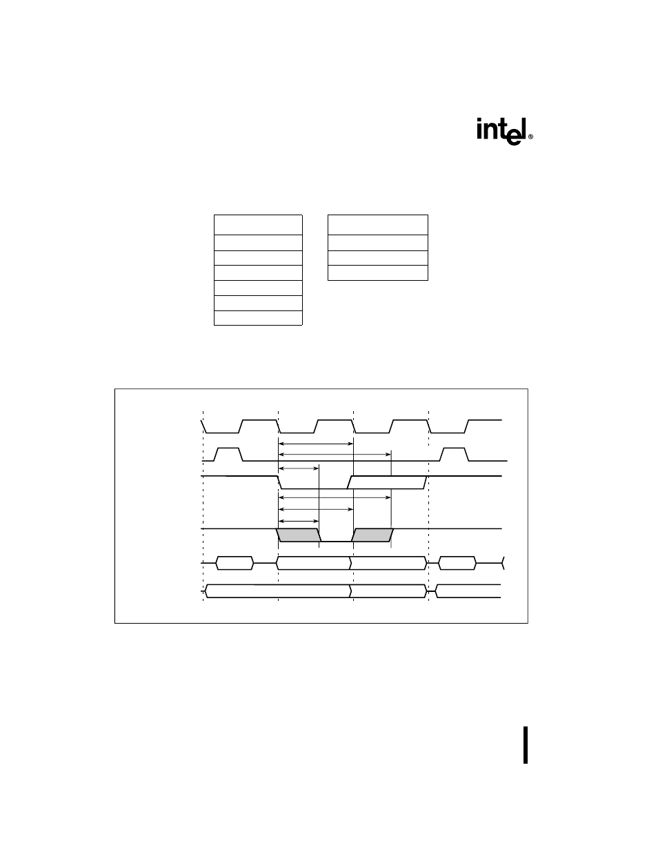
EXTERNAL BUS CYCLES, REAL-TIME WAIT STATES
Figure 13. External Bus Cycle: Code Fetch/Data Read (Nonpage Mode)
Table 12. Real-time Wait Timing Symbol Definitions
Signals
Conditions
A
Address
L
Low
D
Data
X
Hold
C
WCLK
V
Setup
Y
WAIT#
W
WR#
R
RD#/PSEN#
A0-A7
WCLK
ALE
RD#/PSEN#
WAIT#
P0
P2
A8-A15
A5000-01
State 1
State 2
State 3
State 1 (next cycle)
T
CLYX
min
T
CLYV
A0-A7
D0-D7
stretched
A8-A15
stretched
RD#/PSEN# stretched
T
CLYX
max
T
RLYV
T
RLYX
max
T
RLYX
min
This manual is related to the following products: