Figures, Figure 1. 8xc251sa/sb/sp/sq block diagram, Preliminary – Intel 8XC251SA User Manual
Page 3
PRELIMINARY
3
8XC251SA/SB/SP/SQ HIGH-PERFORMANCE CHMOS MICROCONTROLLER
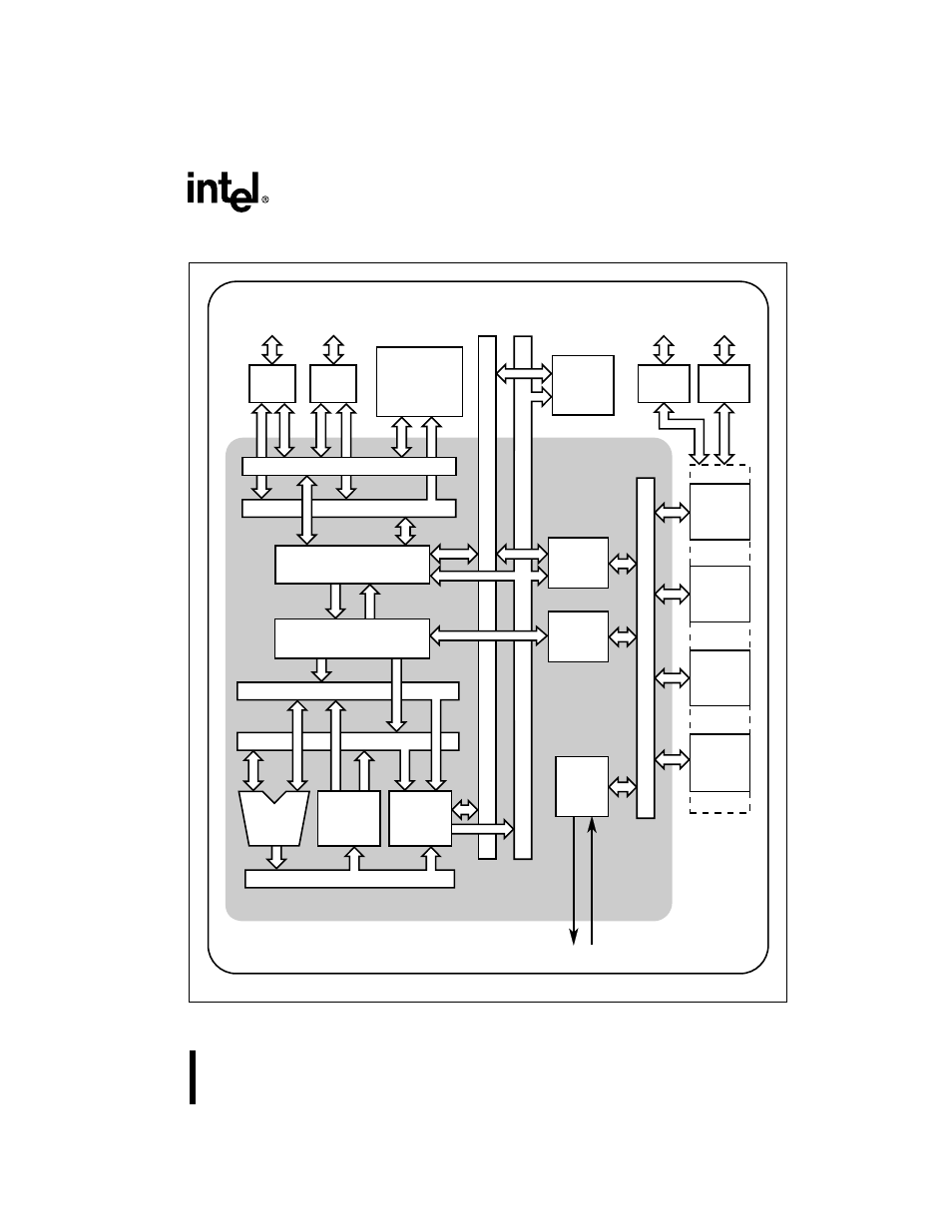
Figure 1. 8XC251SA/SB/SP/SQ Block Diagram
SRC2 (8)
Code Address (24)
Clock & Reset
Code Bus (16)
Data RAM
512 Bytes
or
1024 Bytes
Code
OTPROM/ROM
8 Kbytes
or
16 Kbytes
Watchdog
Timer
Timer/
Counters
PCA
Serial I/O
Peripherals
Port 2
Drivers
P2.7:0
Port 0
Drivers
P0.7:0
Port 3
Drivers
P3.7:0
Port 1
Drivers
P1.7:0
Data Address (24)
Data Bus (8)
Memory Address (16)
MCS
®
251 Microcontroller Core
System Bus and I/O Ports
I/O Ports and
Peripheral Signals
SRC1 (8)
IB Bus (8)
Peripheral
Interface
Interrupt
Handler
Clock
&
Reset
Bus Interface
Instruction Sequencer
DST (16)
ALU
Data
Memory
Interface
Memory Data (16)
Register
File
8XC251SA/SB/SP/SQ Microcontroller
A4214-01
This manual is related to the following products: