Diagram 2 – Impex PRO 5 User Manual
Page 6
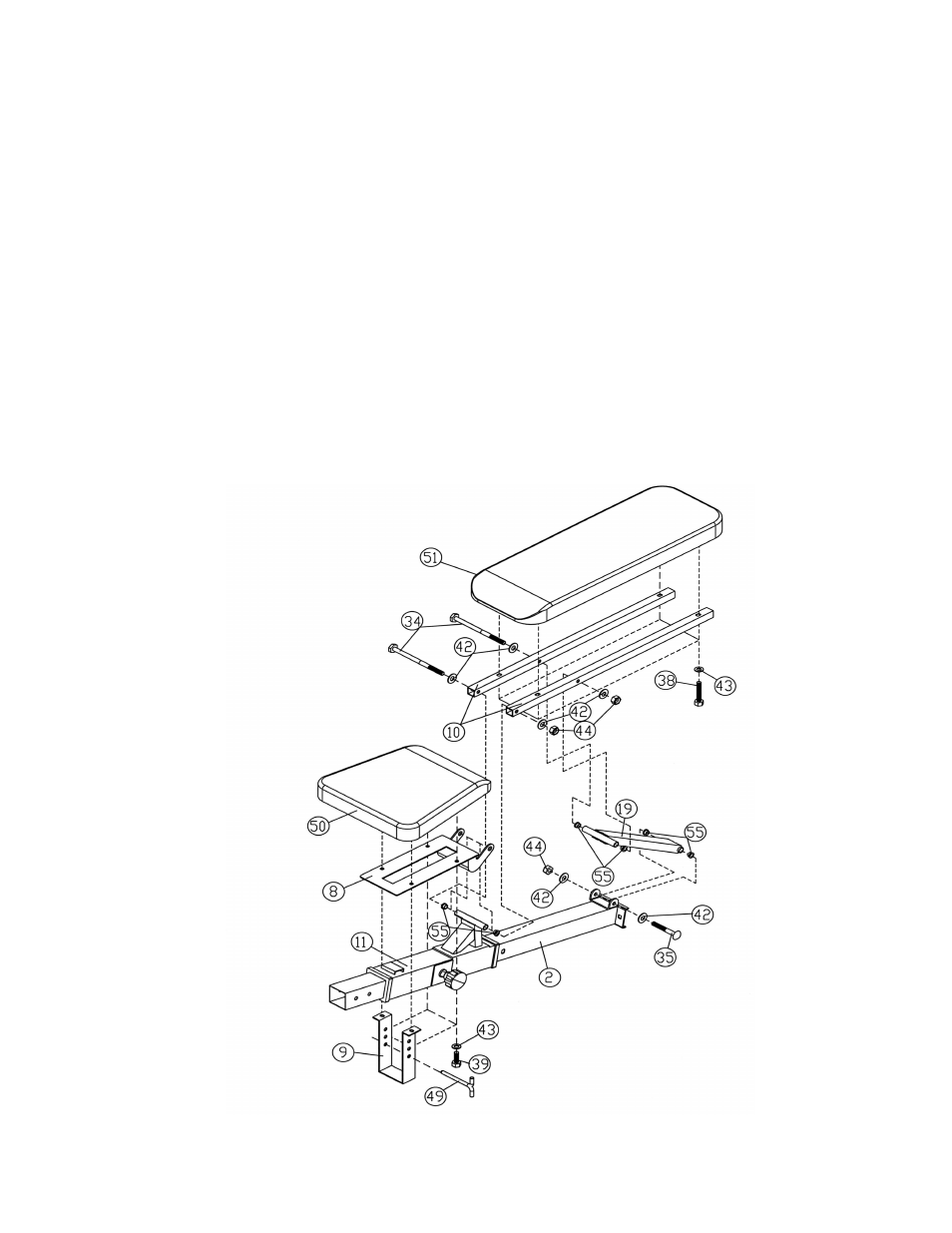
STEP 2 (See Diagram 2)
A.) Attach the Seat Bracket (#8) to the pivot on the Sliding Block (#11). Plug two
∅
5/8” x 3/8”
Bushings (#55) to the holes, one on each side. Attach two Backrest Supports (#10) to the
Bushings. Align the holes and secure them with one M10 x 7 ¼” Hex Bolt (#34), two
∅
¾”
Washers (#42), and one M10 Aircraft Nut (#44).
B.) Attach two
∅
5/8” x 3/8” Bushings (#55) to the end opening on the Backrest Incline Support
(#19). Place the Backrest Incline Support (#19) in between the two Backrest Supports
(#10). Align the holes and secure them with one M10 x 7 ¼” Hex Bolt (#34), two
∅
¾”
Washers (#42), and one M10 Aircraft Nut (#44).
C.) Attach two
∅
5/8”x3/8” Bushings (#55) to the other end of the Backrest Incline Support.
Attach the End to the bracket on the back of the Main Seat Support (#2). Secure it with one
M10 x 3 ¼” Allen Bolt (#35), two
∅
¾” Washers (#42), and one M10 Aircraft Nut (#44).
D.) Attach the Backrest Board (#51) to the Backrest Supports (#10). Secure it with four M8 x 1
½” Allen Bolts (#38) and
∅
5/8” Washers (#43).
E.) Attach the Seat Pad (#50) to the Seat Bracket (#8). Secure the two back holes with two M8
x 5/8” Allen Bolts (#39) and
∅
5/8” Washers (#43). Secure the two front holes with a Seat
Incline Adjustment (#9), two M8 x 5/8” Allen Bolts (#39), and
∅
5/8” Washers (#43). Insert
a Lock Pin (#49) into the selected hole on the Adjustment to hold the desired incline.
DIAGRAM 2
5