Flash bios protect (jp8), Flash bios write-enable voltage (jp13) – Intel SBC-455 User Manual
Page 41
Chapter 2 Installation 33
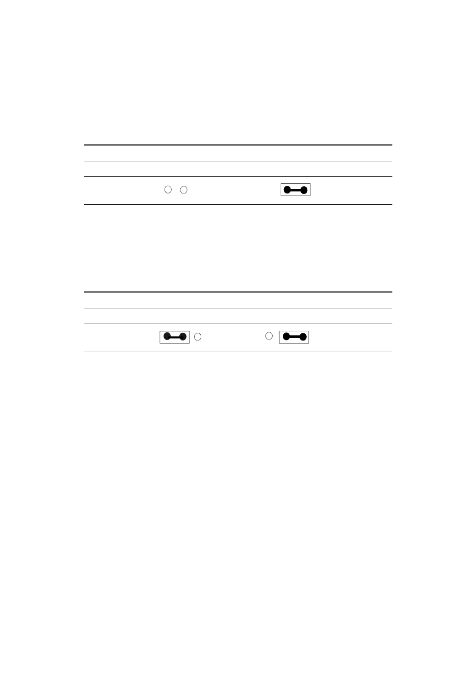
Flash BIOS Protect (JP8)
You can set the JP8 to protect BIOS write-enable. The configura-
tion is as follows:
Flash BIOS Protect (JP8)
Write protect (default)
Write-enable
Flash BIOS Write-enable Voltage (JP13)
This jumper sets the voltage supplied to the Flash BIOS Write-
enable. The figure below shows the proper jumper settings for
both 5V and 12V voltage.
Flash BIOS Write-enable Voltage (JP13)
5 V (default)
12 V
See also other documents in the category Intel Computer Accessories:
- RAID AXXRSBBU6 (14 pages)
- IA-32 (636 pages)
- Evaluation Platform Board Manual RN (88 pages)
- ZT8101 (124 pages)
- CELERON 200 (53 pages)
- 210T (24 pages)
- AXXSW1GB (220 pages)
- I/O Controller Hub 6300ESB (14 pages)
- ARCHITECTURE IA-32 (568 pages)
- D15343-003 (166 pages)
- 1520 (176 pages)
- SR1450 (87 pages)
- 410 (60 pages)
- 460T (150 pages)
- cPCI-7200 (71 pages)
- 82600 (40 pages)
- 4.0A (10 pages)
- CONTROLLERS 413808 (824 pages)
- IXM5414E (294 pages)
- 520T (31 pages)
- NuPRO-850 (50 pages)
- Ethernet Switch Boards (52 pages)
- Express Hub (4 pages)
- SGI Altix 450 (198 pages)
- OPEN (660) 120/140/150 II (160 pages)
- 130T (18 pages)
- Express 100BASE-T4 (43 pages)
- PCI-7200 (65 pages)
- NetStructure 470 (155 pages)
- EXPRESS 330T (16 pages)
- TOUCH-N-MOW 120000 (12 pages)
- ETX CD (91 pages)
- SRW224P (2 pages)
- 410T (40 pages)