Installing the glide tip (figure 3), Replacing fixed wheels/swivel casters, Tightening swivel casters (figure 4) – Invacare 6266 User Manual
Page 4
LEG EXTENSIONS AND
Part No. 1089633
WHEELED WALKER ACCESSORIES
4
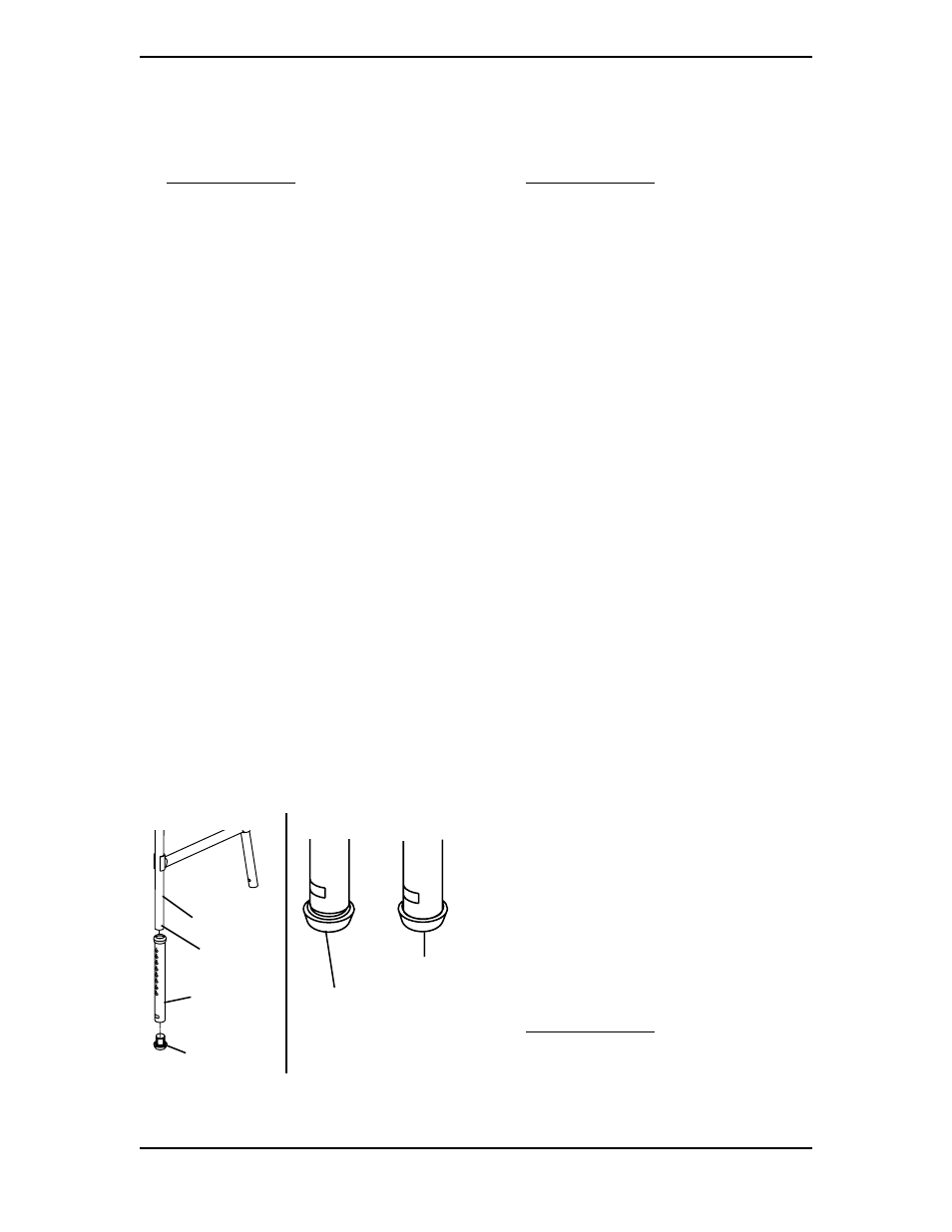
INSTALLING THE GLIDE
TIP (FIGURE 3)
NOTE: Refer to INSTALLATION WARNINGS in
the SAFETY SUMMARY of this instruction sheet.
1. Depress the snap buttons on the walker
frame to remove the rear leg extension
from the walker.
2. Firmly grasp the leg extension and
perform one of the following:
A. Remove the EXISTING glide tip from
the leg extension.
B. Remove the rubber tip from the leg
extension.
NOTE: When properly installed, the tube edge will
rest inside the top edge of the new glide tip. If the
tube edge is visible, the tip is not properly installed.
3. Insert the NEW glide tip firmly into the
leg extension.
4. Ensure the NEW glide tip is properly
installed as shown in DETAIL "A" of
FIGURE 3. If necessary, tap new glide tip
into position.
5. Depress the snap button and install the
leg extension with NEW glide tip onto
the walker frame leg. Ensure that the
snap button of each leg fully protrudes
through the desired adjustment hole and
legs are adjusted so the walker sits level.
6. Repeat STEPS 1-5 on remaining rear leg
extension.
REPLACING FIXED
WHEELS/SWIVEL CASTERS
NOTE: Refer to the INSTALLATION WARNINGS
in the SAFETY SUMMARY of this instruction sheet.
FIXED WHEELS - MODEL NOS.
6270 AND 6271 (FIGURE 1)
Tools Required:
7/16-inch Boxed End Wrench (QTY. 2)
1. Position one (1) wrench on the hex
screw and remove the locknut by using
the other wrench and turning COUN-
TERCLOCKWISE.
2. Remove the washers, wheel, bushing and
hex screw that secure the wheel to the
leg extension.
3. Inspect washers, bushing and hex screw
for wear and/or damage and replace if
necessary.
4. To install new wheel, reverse STEPS 1-2.
SWIVEL CASTERS - MODEL NOS.
6273 AND 6267 (FIGURE 4)
Tools Required:
10-inch crescent wrench
1. Grip leg tube and using the crescent
wrench, apply to hex nut.
2. Loosen swivel caster and unscrew from
swivel caster housing.
3. Inspect swivel caster housing and leg
tube for any damage. If damaged, replace
immediately.
4. Insert new swivel caster by screwing it
into swivel caster housing and tightening
with the crescent wrench.
TIGHTENING SWIVEL
CASTERS (FIGURE 4)
NOTE: Refer to the INSTALLATION WARNINGS
in the SAFETY SUMMARY of this instruction sheet.
1. Remove swivel wheel attachments from
front legs by depressing snap button.
2. Hold one (1) swivel wheel attachment with
the wheel up as shown in FIGURE 4.
FIGURE 3 - INSTALLING THE
GLIDE TIP
Glide Tip
PROPERLY
Installed
Glide Tip
IMPROPERLY
Installed
DETAIL "A"
Walker
Frame Leg
Snap
Button
Leg Tube
Glide
Tip