Diagram 4 – Impex SM-600 User Manual
Page 8
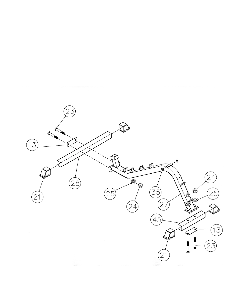
STEP 4 (See Diagram 4)
A.) Attach the rear of the Bench Main Base Frame (#27) to the Bench Rear Stabilizer
(#28). Secure it with one 4 ¾” x 2” Bracket (#13), two M10 x 2 ¾” Carriage Bolts
(#23), two Ø ¾” Washers (#25), and two M10 Aircraft Nuts (#24).
B.) Attach the front of the Bench Main Base Frame (#27) to the Bench Front Stabilizer
(#45). Secure it with one 4 ¾” x 2” Bracket (#13), two M10 x 2 ¾” Carriage Bolts
(#23), two Ø ¾” Washers (#25), and two M10 Aircraft Nuts (#24).
C.) Push four 2” Stabilizer End Caps (#21) onto both ends of the Front & Rear Stabilizers.
D.) Plug two Ø ½” Bushings (#35) onto both ends of the pivot on the Bench Main Base
Frame (#27).
DIAGRAM 4
7
See also other documents in the category Impex Sports and recreation:
- IGS-09 (11 pages)
- SAG-44.1 (10 pages)
- TSA-5682 (14 pages)
- MWM-1840 (29 pages)
- IGS-10 (10 pages)
- TC-6000 (12 pages)
- MWB-715N (12 pages)
- CR 5 (26 pages)
- MD-823 (15 pages)
- PL-43211 (14 pages)
- PL 10510 (12 pages)
- WM-1505 (22 pages)
- PHE1000 (20 pages)
- TSA-5762 (14 pages)
- IGS-5683 (13 pages)
- DBR 400 (7 pages)
- MWM7150 (21 pages)
- DBR 90 (11 pages)
- CG 1400 (24 pages)
- SB 208 (9 pages)
- IGS-02 (10 pages)
- MWB-356 (13 pages)
- AX-PWR7 (21 pages)
- MWB-855 (11 pages)
- TSA-410 (10 pages)
- TSA-41 (7 pages)
- WM 1403 (22 pages)
- DBR 92 (11 pages)
- MARCY TPL-40 (3 pages)
- MSS-1280 (27 pages)
- JD 2 (8 pages)
- PHC-700 (12 pages)
- Gold's Gym WMGG-224 (11 pages)
- MWM 800 (23 pages)
- WM-356 (13 pages)
- EVE-720 (13 pages)
- BF-1201 (22 pages)
- PT 360 (9 pages)
- CB-200 (11 pages)
- Olympic Cage (24 pages)
- EVE-900 (21 pages)
- PT-36 (7 pages)
- PHC-PWR9 (22 pages)
- MWM-1558 (20 pages)
- MWB-4360 (33 pages)