Jumper setting, 3 jumper setting – ICP DAS USA PCI-P16C16 User Manual
Page 11
1.4.3. Jumper Setting
• For PCI-P8R8 / P16R16 / P16C16 / P16POR16
You can change the I/O card configuration simply by setting the
jumpers on this board. Each digital input channel can be jumper-
configured as a single-pole, RC filter with a time constant of 1.2 ms. The
table listed below shows each digital input channel and the
corresponding jumper.
Jumper Channel Jumper
Channel
JP1 DI0 JP9 DI8
JP2 DI1 JP10 DI9
JP3 DI2 JP11 DI10
JP4 DI3 JP12 DI11
JP5 DI4 JP13 DI12
JP6 DI5 JP14 DI13
JP7 DI6 JP15 DI14
JP8 DI7 JP16 DI15
Table 1-2. Jumper assignment.
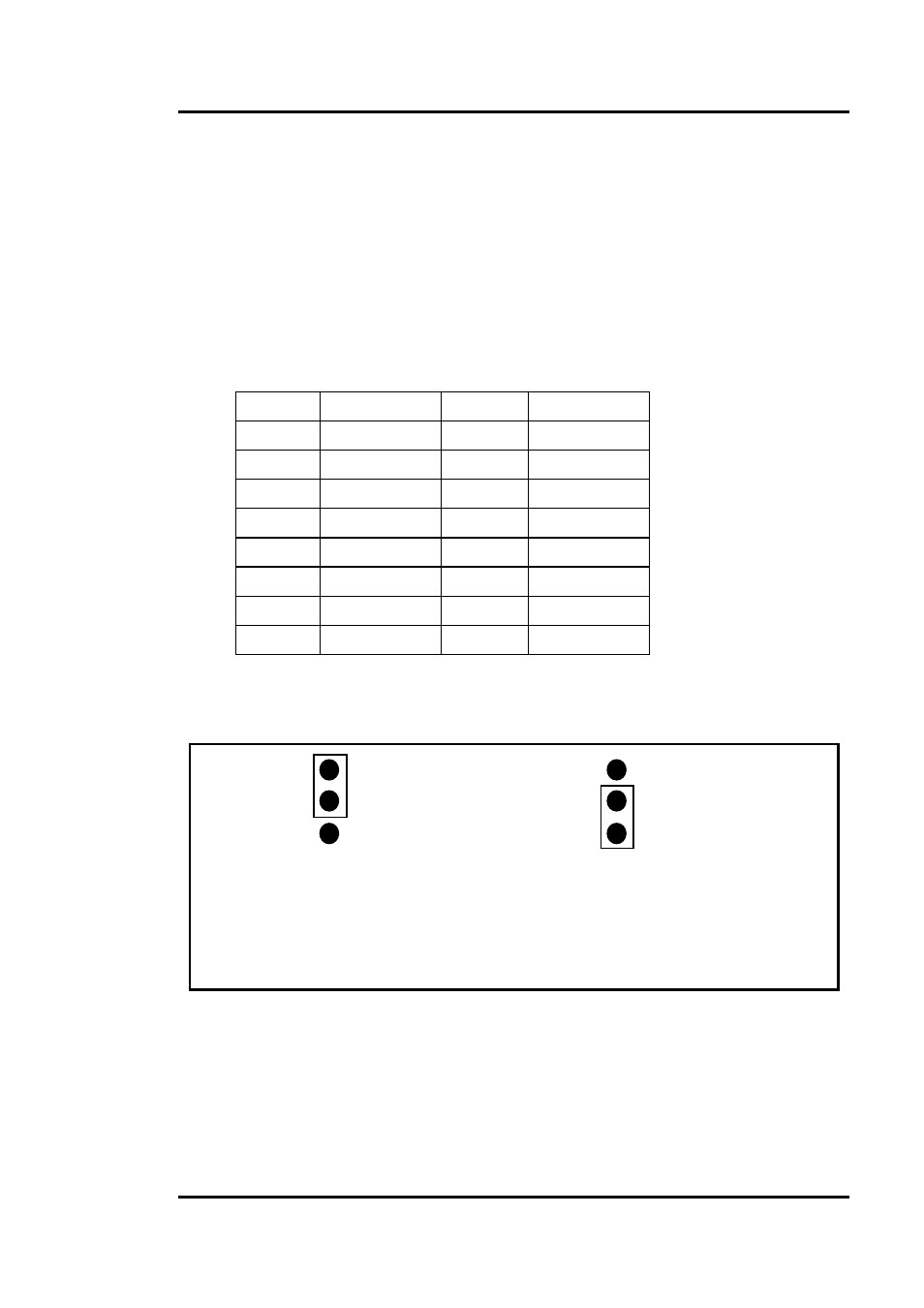
The figure below shows how to select the digital input type :
Figure 1-6. Jumper Settings.
Without Filter
For DC Signal
(Default Settling)
With AC Filter
For AC Signal
1
2
3
1
2
3
If you are using
AC input signals
, you must short
AC FILTER
pin2-3 of the corresponding jumpers. If you are using
DC input signals
,
the
AC FILTER
is optional. If the DC input signal response is less than
20
µs, set the filter to off. If you want a slow response (about 5 to 10 ms)
to reject either noise or contact bouncing, short AC FILTER Pin2-3.
PCI-P8R8/P16R16/P16C16/P16POR16 User’s Manual (Ver.2.2, 2005/5/5) …
11