Smith machine assembly instruction – Impex PHE 9000 User Manual
Page 7
SMITH MACHINE ASSEMBLY INSTRUCTION
Tools Required Assembling the Machine: Two Adjustable Wrenches and Allen
Wrenches. NOTE: It is strongly recommended two or more people assembling this
machine to avoid possible injury.
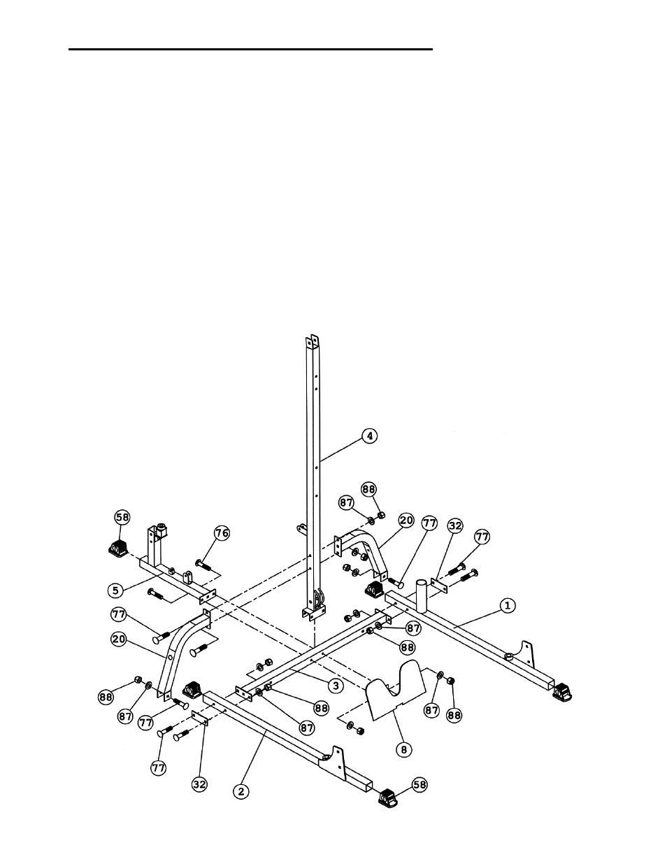
STEP 1 (See Diagram 1)
A.) Connect the Left & Right Base Frame (#1 & 2) by a Cross Brace (#3) in the mid-span.
Secure each end of the Cross Brace to each Base Frame with two M10 x 2 ¾” Carriage
Bolts (#77), one 4 ¾” x 2” Bracket (#32), two Ø ¾” Washers (#87), and two M10 Aircraft
Nuts (#88). NOTE: DO NOT tighten the Nuts and Bolts yet.
B.) Attach the Middle Vertical Frame (#4), the Rear Base Frame (#5) and the Foot Plate (#8)
to the Cross Brace (#3). Align the holes and secure them together with two M10 x 3”
Carriage Bolts (#76), Ø ¾” Washers (#87), and M10 Aircraft Nuts (#88).
C.) Attach the top of each Weight Post Support (#20) to the Middle Vertical Beam (#4) from
each side. Attach the bottom of each Weight Post Support to the Cross Brace (#3).
D.) Secure the two Weight Post Supports (#20) to the Middle Vertical Frame (#4) with two
M10 x 2 ¾” Carriage Bolts (#77), Ø ¾” Washers (#87), and M10 Aircraft Nuts (#88).
E.) Secure the bottom of each Weight Post Support to the Cross Brace with one M10 x 2 ¾”
Carriage Bolt (#77), Ø ¾” Washer (#87), and M10 Aircraft Nut (#88).
F.) Cover all ends on the Base Frame with five 2” End Caps (#58).
6