Front panel hd audio header, Connecting the hi-speed usb 2.0 header – Intel D945GCLF User Manual
Page 31
Installing and Replacing Desktop Board Components
31
Front Panel HD Audio Header
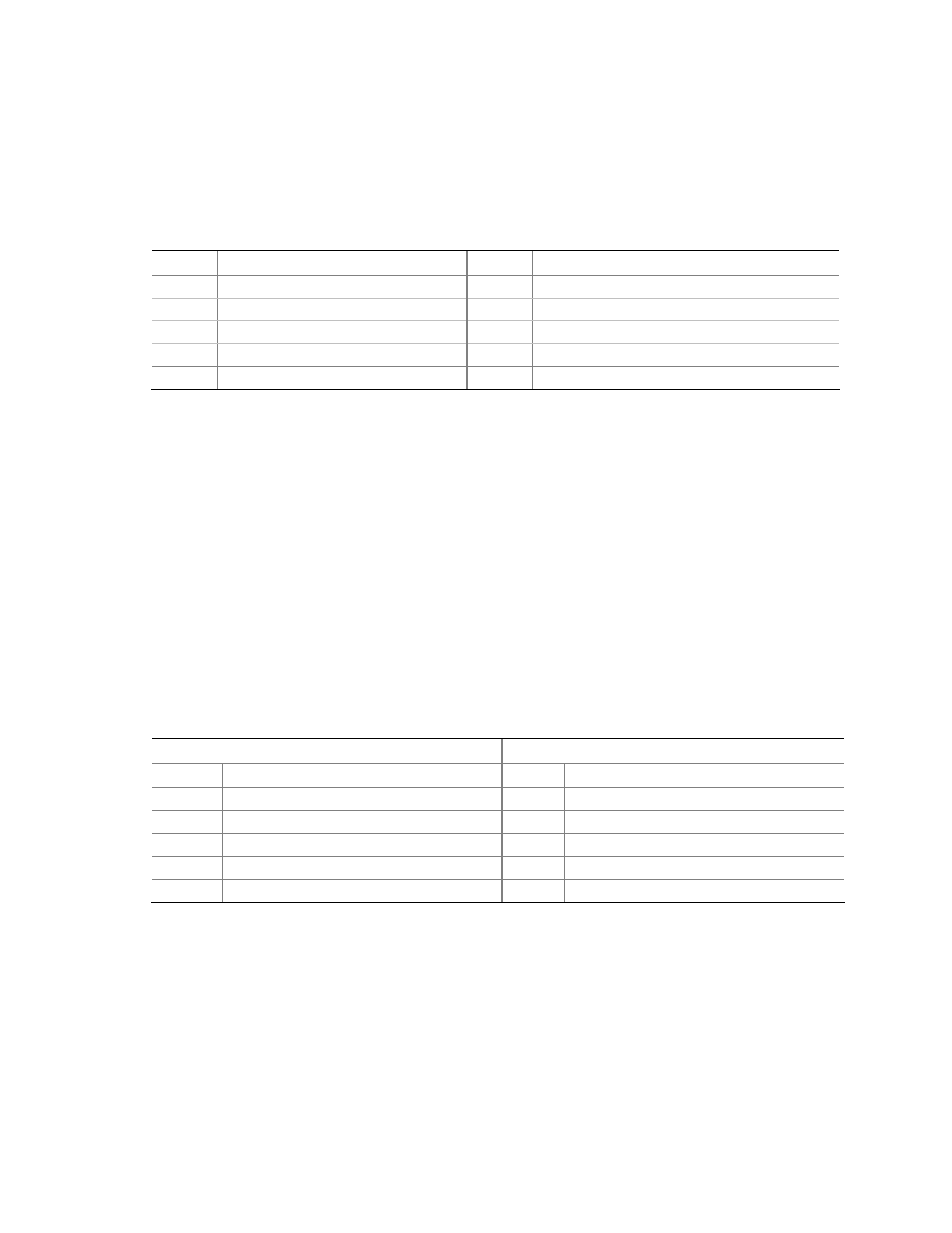
Figure 11, A shows the location of the front panel audio header. Table 4 shows the pin
assignments for the front panel audio header.
Table 4. Front Panel Audio Header Signal Names for Intel High Definition
Audio
Pin Signal
Name
Pin Signal
Name
1
PORT 1L
2
GND
3 PORT
1R
4 PRESENCE#
5 PORT
2R
6 SENSE1_RETURN
7 SENSE_SEND
8 KEY
(no
pin)
9 PORT
2L
10
SENSE2_RETURN
To install a cable that connects a front panel audio solution to the front panel audio
header, follow these steps:
1. Observe the precautions in “Before You Begin” on page 21.
2. Turn off all peripheral devices connected to the computer. Turn off the computer
and disconnect the AC power cord.
3. Remove the cover.
4. Install a correctly keyed and shielded front panel audio cable.
Connecting the Hi-Speed USB 2.0 Header
Before connecting to the USB 2.0 header, observe the precautions in "Before You
Begin" on page 21. See Figure 11, B on page 30 for the location of the USB 2.0
header.
Table 5 shows the pin assignments for the headers.
Table 5. Hi-Speed USB 2.0 Header Signal Names
USB Port A
USB Port B
Pin
Signal Name
Pin
Signal Name
1 Power
2 Power
3 D-
4 D-
5 D+
6 D+
7 Ground
8 Ground
9 Key
10
No
connect
Note: USB ports may be assigned as needed.