Diagram 2 – Impex IRONGRIP IGS-04 User Manual
Page 6
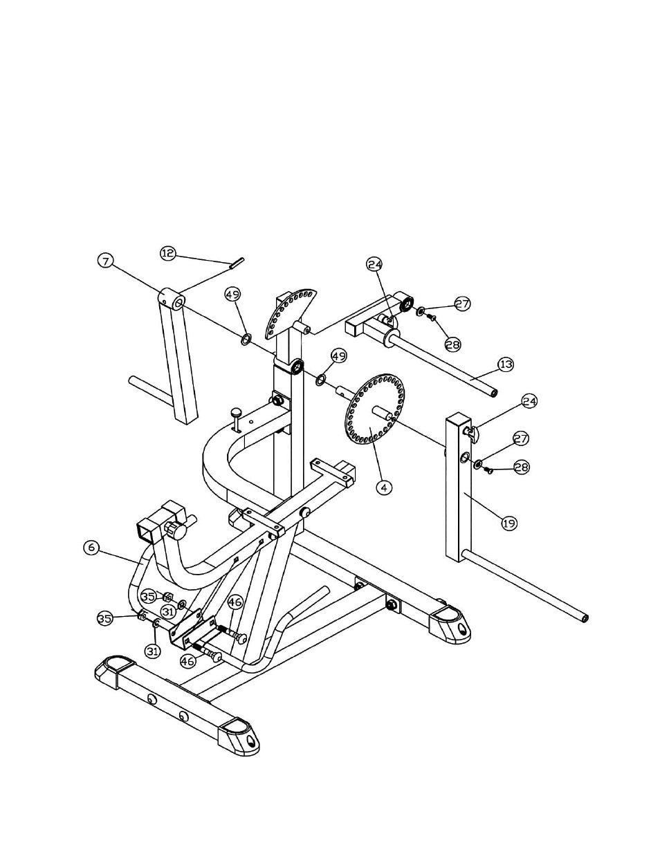
STEP 2 (See Diagram 2)
A.) Slide a
∅
1 ½” Plastic Spacer (#49) onto the Axle on the Adjustment Plate (#4). Insert
the Axle through the Pivot Barrel on the Main Frame. Slide another Spacer onto the
Axle.
B.) Slide the Weight Holder (#7) onto the Axle and align the holes. Insert a Roll Pin (#12)
through the hole and drive it in with a hammer.
C.) Attach the Leg Developer Frame (#19) onto the Axle on the Adjustment Plate (#4).
Secure it with one M10 x ¾” Allen Bolt (#28) and
∅
1 3/8” Washer (#27).
D.) Slide the Knee-lock Frame (#13) onto the pivot axle on the Main Frame. Secure it with
one M10 x ¾” Allen Bolt (#28) and
∅
1 3/8” Washer (#27).
E.) Attach the open bracket on the Handle (#6) to the Seat Support (#2). Secure it with two
M10 x 2 ¾” Carriage Bolts (#46),
∅
¾” Washers (31), and M10 Aircraft Nuts (#35).
DIAGRAM 2
5
- IGS-09 (11 pages)
- SAG-44.1 (10 pages)
- TSA-5682 (14 pages)
- MWM-1840 (29 pages)
- IGS-10 (10 pages)
- TC-6000 (12 pages)
- MWB-715N (12 pages)
- CR 5 (26 pages)
- MD-823 (15 pages)
- PL-43211 (14 pages)
- PL 10510 (12 pages)
- WM-1505 (22 pages)
- PHE1000 (20 pages)
- TSA-5762 (14 pages)
- IGS-5683 (13 pages)
- DBR 400 (7 pages)
- MWM7150 (21 pages)
- DBR 90 (11 pages)
- CG 1400 (24 pages)
- SB 208 (9 pages)
- IGS-02 (10 pages)
- MWB-356 (13 pages)
- AX-PWR7 (21 pages)
- MWB-855 (11 pages)
- TSA-410 (10 pages)
- TSA-41 (7 pages)
- WM 1403 (22 pages)
- DBR 92 (11 pages)
- MARCY TPL-40 (3 pages)
- MSS-1280 (27 pages)
- JD 2 (8 pages)
- PHC-700 (12 pages)
- Gold's Gym WMGG-224 (11 pages)
- MWM 800 (23 pages)
- WM-356 (13 pages)
- EVE-720 (13 pages)
- BF-1201 (22 pages)
- PT 360 (9 pages)
- CB-200 (11 pages)
- Olympic Cage (24 pages)
- EVE-900 (21 pages)
- PT-36 (7 pages)
- PHC-PWR9 (22 pages)
- MWM-1558 (20 pages)
- MWB-4360 (33 pages)