Diagram 2 – Impex PREMIER User Manual
Page 6
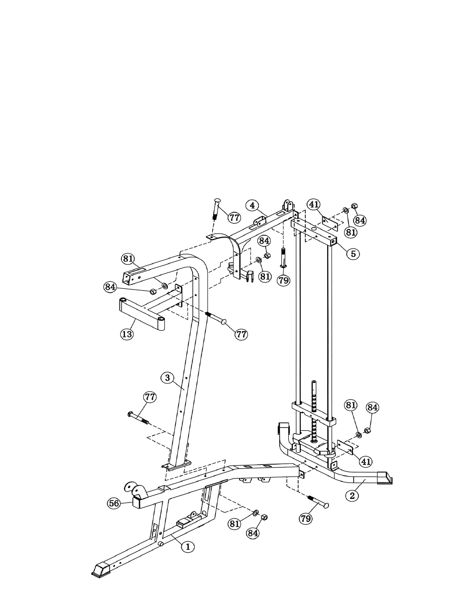
STEP 2 (See Diagram 2)
A.) Attach the Main Base Frame (#1) to the Rear Stabilizer (#2). Secure it with one Bracket
(#41), two M10 x 2 ¾” Carriage Bolts (#79),
∅
¾” Washers (#81), and M10 Aircraft Nuts
(#84). Do not tighten the Nuts and Bolts yet.
B.) Attach the bottom of the Vertical Beam (#3) to the Main Base Frame (#1). Secure it with two
M10 x 3 ½” Carriage Bolts (#77),
∅
¾” Washers (#81), and M10 Aircraft Nuts (#84). Do not
tighten the Nuts and Bolts yet.
C.) Attach the Butterfly Support Frame (#13) to the front of Vertical Beam (#3). Attach the front
end of Upper Frame (#4) to the back of Vertical Beam. Align the holes and secure them
together with three M10 x 3 ½” Carriage Bolts (#77),
∅
¾” Washers (#81), and M10 Aircraft
Nuts (#84).
D.) Attach the rear end of Upper Frame (#4) to the Top Socket Assembly (#5). Secure it with
one Bracket (#41), two M10 x 2 ¾” Carriage Bolts (#79),
∅
¾” Washers (#81), and M10
Aircraft Nuts (#84). Securely tighten all the Nuts and Bolts previously installed.
DIAGRAM
2
5