Pin assignments mechanical specifications, Motor performance, Speed-torque – Intelligent Motion Systems MFM Motion Detector User Manual
Page 3: Dimensions in inches (mm)
MForce PowerDrive – Motion Control
REV052307
3
PIN ASSIGNMENTS
MECHANICAL SPECIFICATIONS
Dimensions in Inches (mm)
3.473
(88.21)
2X 0.580
(2X 14.73)
Ш 0.187 ±0.01
(Ш 4.75 ±0.25)
2X #8 Screws
for End Mount
Connector Options
3.00 ±0.01
(76.2 ±0.25)
2.116
(53.75)
0.225
(5.72)
BOTTOM VIEW
FRONT VIEW
3.473
(88.21)
Ø 0.160 ±0.01 Thru
(Ø 4.06 ±0.25 Thru)
4X #6 Screws
for Flat Mount
0.308 TYP.
(7.82 TYP.)
2.931 TYP.
(74.45 TYP.)
3.897
(98.98)
0.417 TYP.
(10.59 TYP.)
0.160 ±0.01
(4.06 ±0.25)
2.950
(74.93)
Connector Options
P3
P1
P4
P2
P3
P1
P4
P2
P3
P1
P4
P2
Pluggable Locking Wire Crimp
Remote Encoder Option
CANopen with DB9
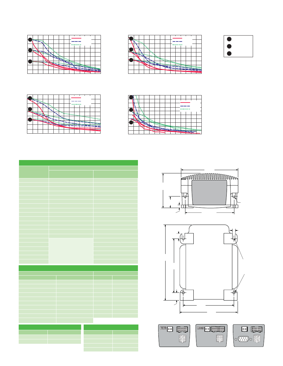
MOTOR PERFORMANCE —
Speed-Torque
200
225
175
150
125
100
75
50
25
0
141
159
124
106
88
71
53
35
18
0
Torque in Oz - In
Torque in N - cm
24 VDC
45 VDC
75 VDC
1000
(300)
2000
(600)
3000
(900)
4000
(1200)
5000
(1500)
6000
(1800)
7000
(2100)
Speed in Full Steps per Second (RPM)
C
B
A
NEMA 23 — 2.4 Amps RMS
200
225
175
150
125
100
75
50
25
0
141
159
124
106
88
71
53
35
18
0
Torque in Oz - In
Torque in N - cm
24 VDC
45 VDC
75 VDC
1000
(300)
2000
(600)
3000
(900)
4000
(1200)
5000
(1500)
6000
(1800)
7000
(2100)
Speed in Full Steps per Second (RPM)
C
B
A
NEMA 23 — 3.0 Amps RMS
200
225
175
150
125
100
75
50
25
0
141
159
124
106
88
71
53
35
18
0
Torque in Oz - In
Torque in N - cm
24 VDC
45 VDC
75 VDC
1000
(300)
2000
(600)
3000
(900)
4000
(1200)
5000
(1500)
6000
(1800)
7000
(2100)
Speed in Full Steps per Second (RPM)
C
A
B
NEMA 23 — 6.0 Amps RMS
NEMA 34 — 6.3 Amps RMS
900
1000
800
700
600
500
400
300
200
100
0
0
1000
(300)
2000
(600)
3000
(900)
4000
(1200)
5000
(1500)
6000
(1800)
7000
(2100)
Speed in Full Steps per Second (RPM)
Torque in Oz - In
T
orque in N - cm
465
494
423
706
635
353
282
211
140
71
45 VDC
75 VDC
24 VDC
C
B
A
A
B
C
Single Stack
Double Stack
Triple Stack
P2: COMM CONNECTOR
RS-422/485
CANopen
Friction Lock Wire Crimp
Function
DB9
Function
Pin 1
TX +
Pin 1
No Connect
Pin 2
Comm Ground
Pin 2
CAN Low
Pin 3
RX –
Pin 3
CAN –V
Pin 4
TX –
Pin 4
Aux Power
Pin 5
Aux-Logic (+12 to +24 VDC)
Pin 5
Shield
Pin 6
RX +
Pin 6
CAN –V
Pin 7
RX +
Pin 7
CAN High
Pin 8
RX –
Pin 8
No Connect
Pin 9
TX +
Pin 9
CAN +V
Pin 10
TX –
P1: I/O CONNECTOR
Pluggable Locking
Wire Crimp
Function
Standard
With Optional Remote
Encoder Closed Loop Control
Pin 1
I/O Power
I/O Power
Pin 2
I/O Ground
I/O Ground
Pin 3
I/O 1
I/O 1
Pin 4
I/O 2
I/O 2
Pin 5
I/O 3
I/O 3
Pin 6
I/O 4
I/O 4
Pin 7
I/O 9
I/O 9
Pin 8
I/O 10
I/O 10
Pin 9
I/O 11
I/O 11
Pin 10
I/O 12
I/O 12
Pin 11
Capture/Trip I/O
Capture/Trip I/O
Pin 12
Analog In
Analog In
Pin 13
Step/Clock I/O
Step/Clock I/O
Pin 14
Direction/Clock I/O
Direction/Clock I/O
Pin 15
not applicable
Channel A +
Pin 16
Channel A –
Pin 17
Channel B +
Pin 18
Channel B –
Pin 19
Index +
Pin 20
Index –
P3: POWER CONNECTOR
Wire Crimp
Function
Pin 1
+V (+12 to +75 VDC)
Pin 2
Power/Aux Ground
P4: MOTOR CONNECTOR
Wire Crimp
Function
Pin 1
Phase A
Pin 2
Phase /A
Pin 3
Phase B
Pin 4
Phase /B