Intelligent Motion Systems MDrive34AC User Manual
Mdrive34ac plus microstepping, Quick reference
Mechanical Specifications
MDrive34AC Plus Microstepping Quick Reference R070208
Quick Reference
MDrive34AC Plus
Microstepping
Notes and Warnings
Installation, configuration and maintenance must be carried out by qualified
technicians only. You must have detailed information to be able to carry out this
work. This information can be found in the user manuals.
• Unexpected dangers may be encountered when working with this product!
• Incorrect use may destroy this product and connected components!
The user manuals are not included. You can obtain them from the Internet at:
http://www.imshome.com/mdrive34acplus_mdm.html.
Required for Setup*
PC running Microsoft(r) Windows XP Service Pack 2 or greater.
•
IMS SPI Motor Interface (available online)
•
MD-CS200/201-000 or equivalent Lumberg mating connector/cordset for
•
AC power.
0 to 5 MHz Clock signal for step clock, may be a controller high speed
•
output or signal generator.
SPST switch or controller I/O point to control axis direction.
•
I/O and SPI communications interface (Recommended: IMS MD-
•
CC301-001)
* If you purchased your MDrivePlus with a QuickStart Kit, you have received all
of the connecting cables needed for initial functional setup and system testing.
Getting Started
All documentation, software and resources are available online at:
http://www.imshome.com/mdrive34acplus_mdm.html
Connecting Power and I/O
Your MDrivePlus may be configured with power and I/O combined on a single
connector, or with separate connectors. Please refer to the opposite side of this
document for connecting details and available IMS connectivity options includ-
ing Prototype Development Cables and Mating Connector Kits.
Connecting Communications
Connect IMS USB to SPI communications converter to MDrivePlus and
1.
PC.
Install the communication converter drivers onto PC (available online).
2.
Install and open SPI Motor lnterface.
3.
Apply power to MDrivePlus.
4.
Parameters may be adjusted via two screens, the Motor Settings screen
5.
or the I/O settings screen (shown below), accessible via the View menu.
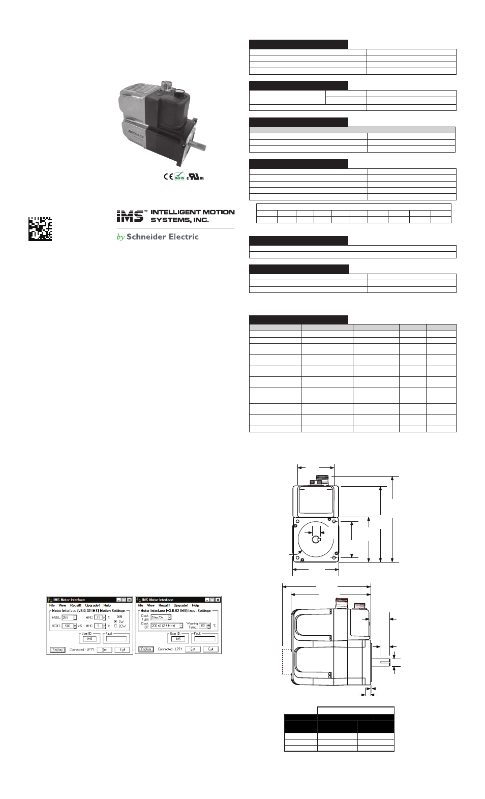
Motor Settings Screen
I/O Settings Screen
All documentation, software, program examples and resources are available
online at: http://www.imshome.com/mdrive34acplus_mdm.html
Specifications
Electrical Specifications
Input Voltage Range (120 VAC MDrive)
95 to 132 VAC @ 50/60 Hz
Input Current (120 VAC MDrive)
4.2 Amps
Input Voltage Range (240 VAC MDrive)
95 to 264 VAC @ 50/60 Hz
Input Current (240 VAC MDrive)
2.1 Amps
Environmental Specifications
Operating Temperature
(non-condensing)
Heat Sink
-40°C to +75°C
Motor
-40°C to +90°C
Sealing (-65 Only)
IP-65 Compliant
Isolated Input Specifications
Step Clock, Direction and Enable
Voltage Range (Sinking or Sourcing)
+5 to +24 VDC
Current (+5V Max)
8.7 mA
Current (+24V Max)
14.6 mA
Motion Specifications
Digital Filter Range
50 nS to 12.9 µS (10 MHz to 38.8 kHz)
Clock Types
Step/Direction, Up/Down, Quadrature
Step Frequency (Max)
5 MHz
Step Frequency Minimum Pulse Width
100 nS
Number of Microstep Resolution Settings
20
Available Microsteps Per Revolution
200
400
800
1000
1600
2000
3200
5000
6400
10000
12800
20000
25000
25600
40000
50000
51200
36000
1
21600
2
25400
3
1=0.01 deg/µstep 2=1 arc minute/µstep 3=0.001 mm/µstep
Protection Specifications
Thermal
Internal Fuse (Line-Neutral Systems Only, Line-Line Systems Require External Fusing)
Temp. Warning Output Specifications
Type
Open Drain
Drain-Source Voltage
+5 to +24 VDC
Drain Current
50 mA
Setup Parameters
Setup Parameters
Name
Function
Range
Units
Default
MHC
Motor Hold Current
0 to 100
Percent
5
MRC
Motor Run Current
1 to 100
Percent
25
MSEL
Microstep Resolution
See Motion
Specifications
µsteps/
Full Step
256
DIR
Motor Direction
Override
0/1
—
CW
HCDT
Hold Current Delay
Time
0 or 2 - 65535
mSec
500
CLK TYPE
Clock Type
See Motion
Specifications
—
Step/
Direction
CLK IOF
Clock Input Filter
50 nS to 12.9 µS
(10 MHz to 38.8
kHz)
nS (MHz)
200 nS
(2.5 MHz)
EN ACT
Enable Active High/
Low
High/Low
—
High
USER ID
User ID
3 Characters
Viewable ASCII
Viewable
ASCII
IMS
WARN TEMP
Warning Temperature
0 to +125
°C
80
Dimensions in inches (mm)
Motor Length
LMAX1
(Single Shaft or
Internal Encoder)
LMAX2
(Control Knob)
Single
6.1 (155.0)
7.1 (180.4)
Double
6.9 (174.3)
7.9 (199.7)
Triple
8.4 (214.3)
9.4 (239.79)
LMAX1
LMAX2
1.46
(37.0)
0.87
(22.0)
Ш 0.55
(Ш 14.0)
0.40
(10.1)
0.08
(2.0)
2.70
(68.4)
3.38 SQ.
(85.8 SQ.)
5.76
(146.2)
6.47
(164.2)
2.74 SQ.
(69.58 SQ.)
Ш 2.87
(Ш 73.0)
3.46
(87.8)
0.63
(16.0)