Diagram 2 – Impex SB 208 User Manual
Page 6
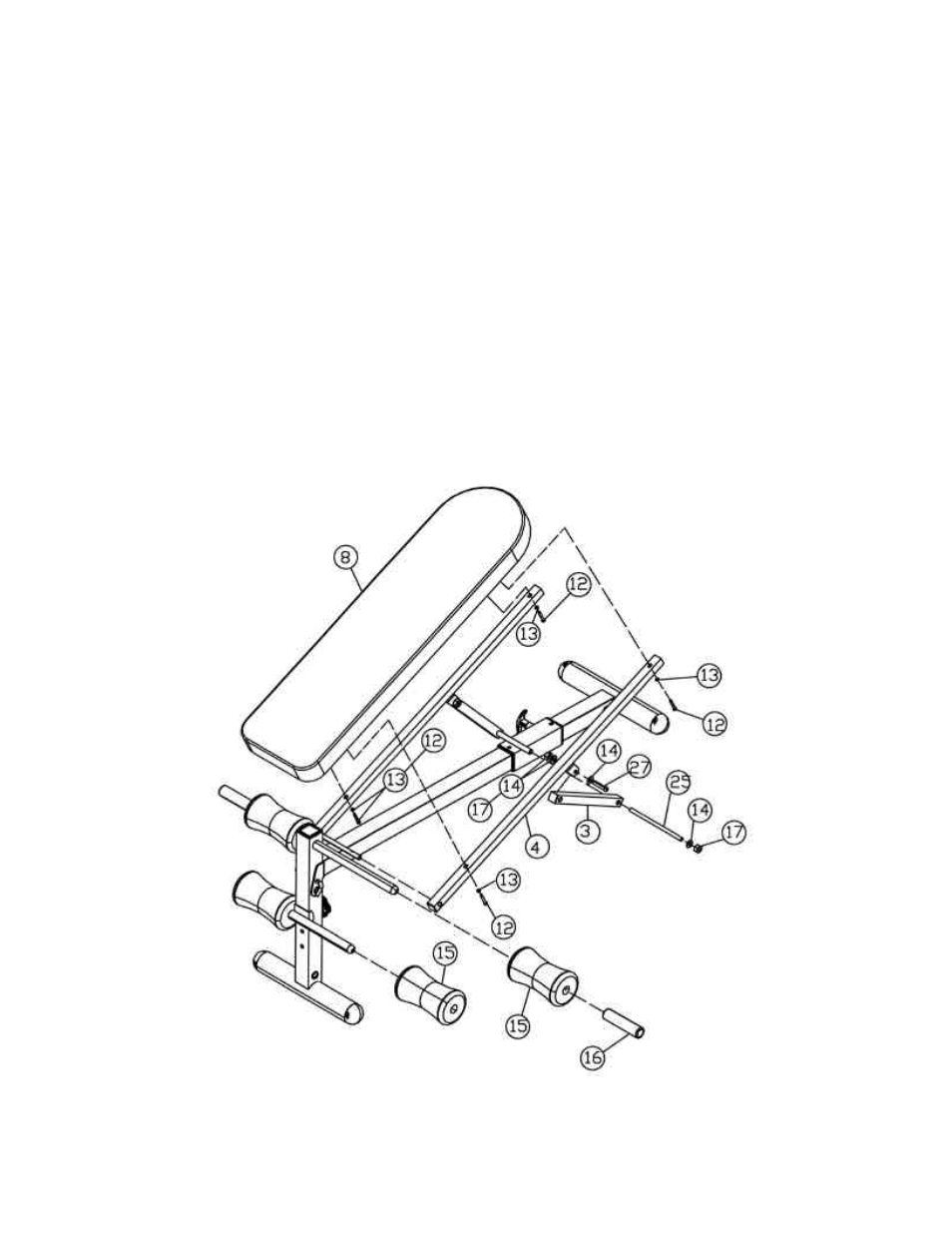
STEP 2 (See Diagram 2)
A.) Attach the holed-side of the Backrest Support Bars (#4) onto both ends of the Pivot on the
Main Frame (#2).
B.) Attach an Incline Support (#3) to the bracket on the Backrest Support Bar (#4). Secure it with a
M10 x 1 ¾
” Allen Bolt (#27), two
∅
7/8” Washers (#14), and one M10 Aircraft Nut (#17). Repeat
the same procedure to install the other side.
C.) Attach the Incline Supports (#3) to the pivot on the Sliding Block (#9). Align the holes and
secure them with a M10 x 7 7/8” Axle (#25), two
∅
7/8” Washers (#14), and two M10 Aircraft
Nuts (#17).
D.) Attach the Backrest Board (#8) to the Backrest Support Bars (#4). Secure it with four M6
Philips Head Screws (#12) and
∅
1/4” Washers (#13).
E.) Insert a Foam Tube (#6) halfway into the hole on the Front Frame (#1). Slide two Foam Rolls
(#15) onto the tube from both sides. Then slide two Foam Grips (#16) onto the tube from both
sides. Slide two Foam Rolls (#15) onto the Cross Tube (#5) from both sides.
DIAGRAM 2
5