English – Middleby Marshall PS314SBI User Manual
Page 9
9
ENGLISH
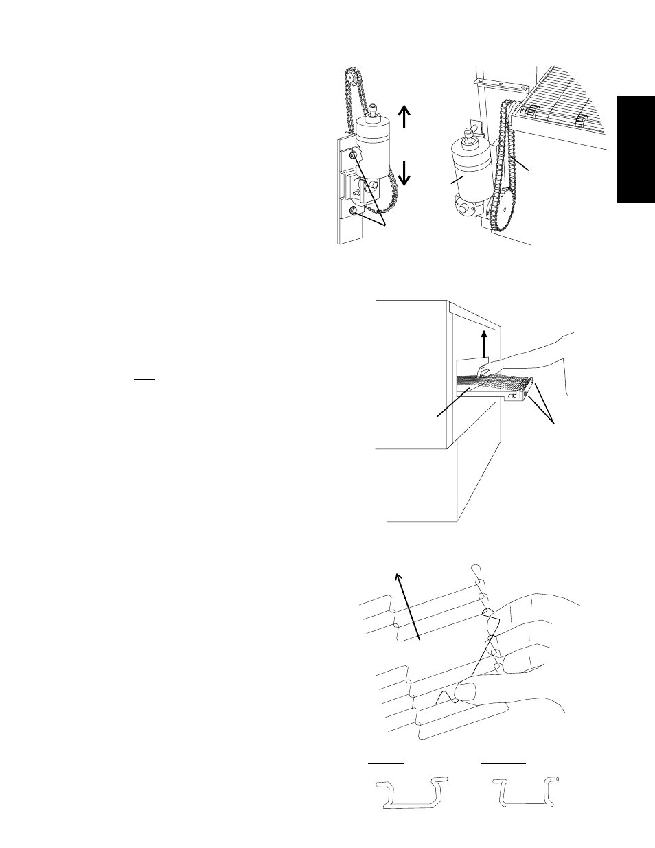
3. Install the drive chain between the conveyor drive sprocket
and the motor sprocket as shown in Figure 2-10. Then,
check the tension of the drive chain. The chain should have
a 1/2" (13mm) deflection.
If necessary, the motor can be repositioned to allow the
chain to be installed, or to correct the tension of the chain
after it is in place. To reposition the motor:
Loosen the two hex head screws that fasten the
conveyor motor's mounting bracket to the oven. The
screws are shown in Figure 2-10.
Raise or lower the motor slightly, as required. Tighten
the two hex screws, and check the chain tension.
Repeat these steps as necessary until the drive chain
has the correct 1/2" (13mm) deflection.
4. Check the tension of the conveyor belt at the IDLER (right)
end of the conveyor, by lifting the center of the belt straight
up with your fingers as shown in Figure 2-11. The belt
should lift between 2-3" (50-75mm). DO NOT OVER-
TIGHTEN THE CONVEYOR BELT.
NOTE:
If necessary, the belt tension can be adjusted by turning the
conveyor adjustment screws, located at the idler (right) end
of the conveyor. See Figure 2-11.
5. Check for freedom of movement of the conveyor belt by
pulling it for about 2-3 feet (60 to 90 cm) with your fingers.
The conveyor must move freely.
6. If necessary, links can be added to or removed from the
conveyor belt to achieve the correct deflection of 2-3" (50-
75mm). If links must be removed from the belt, it can be
reattached to the conveyor as follows:
a. The conveyor belt links must be oriented as shown in
Figure 2-12.
b. The smooth side of the conveyor belt must face UP.
c. Connect the inside master links. Check that the links
are oriented as shown in Figure 2-12.
d. Connect the outside master links. Note that the
outside master links have right and left sides. The
right-side master link has an open hook facing you, as
shown in Figure 2-12.
e. Return to Step 4, above, to re-check the belt tension.
SECTION 2 - INSTALLATION
Figure 2-10 - Drive Motor and Drive Chain
Loosen hex screws and
slide motor up or down to
adjust belt tension
Drive chain
Motor
Figure 2-11 - Conveyor belt tension
Belt deflection
should be 2-3
(50-75mm)
Lift belt straight
up as shown
Adjust tension by
turning screws (2)
Figure 2-12 - Master link orientation
Direction of
travel
Correct outside
master link
orientation
CORRECT inside master
link orientation
INCORRECT inside master
link orientation