English, Vi. final assembly – Middleby Marshall PS314SBI User Manual
Page 10
10
ENGLISH
SECTION 2 - INSTALLATION
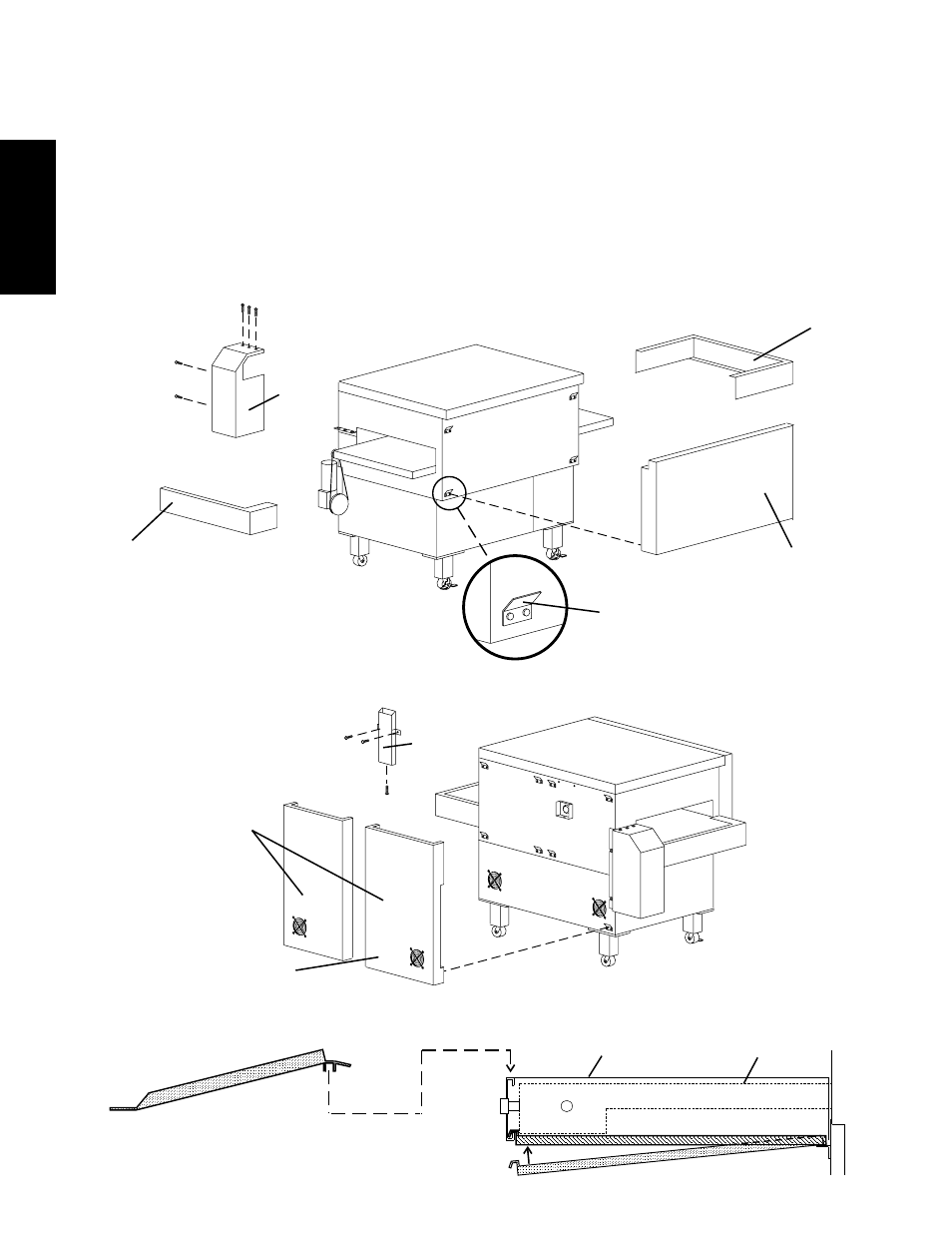
Figure 2-13 - Final Assembly - Front
VI. FINAL ASSEMBLY
1. For gas ovens, attach the flue vent to the rear wall of the oven
as shown in Figure 2-13. Use one #10-16 x 3/8" screw and
two #10-32 x 3/4" screws. All three screws are provided in
the Installation Kit.
2. Install the motor housing, and secure it in place with its five
mounting screws. Two screws are located on the back wall
of the oven, while three are located on the hanger bracket
on the left end panel. See Figure 2-13.
3. Install the conveyor extension covers over the ends of the
conveyor frame. See Figure 2-13.
4. Check that the cool panels are properly mounted, as shown
in Figures 2-13 and 2-14. Slots on the back of the panels
fit over the hangers on the walls of the oven. One cool panel
is attached to the front of the oven, while two are attached
to the rear.
5. Attach the exit tray(s) at the drive (left) end of the conveyor.
See Figure 2-15.
6. Install the crumb trays underneath the conveyor as shown
in Figure 2-15. First, place the inside edge of the tray onto
the bracket attached to the end plug. Then, swing the
outside edge of the tray up and into place.
Figure 2-14 - Final Assembly - Rear
Motor
shroud
3 upper
screws
Extension cover
(idler end)
Front cool
panel
Hangers on oven
wall fit into slots on
cool panels
Extension cover
(drive end)
2 rear
screws
Flue vent
(gas ovens
only)
Figure 2-15 - Final Assembly - Exit Tray(s) and Crumb Trays
2 rear
#10-16 x 3/4"
screws
Rear cool
panels
Drive-end rear
panel notched for
motor shroud
1 bottom
#10-32 x 3/8"
screw
Crumb tray
Exit tray(s)
Conveyor extension
Conveyor frame