Milwaukee COMPOUND MITER SAW User Manual
Page 5
page 5
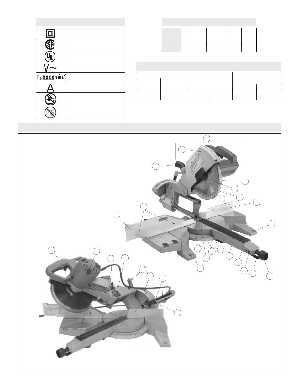
17. Flip fence
18. Face board mounting holes (4)
19. Dust ejection port
20. Trigger
21. Spindle lock
22. Depth adjustment set screw
23. Lock pin
24. Bevel adjustment lever
25. Bevel angle scale
26. Slide rails
27. Slide rail lock
FUNCTIONAL DESCRIPTION
1. Saw head
2. Upper guard
3. Lower guard
4. Blade screw guard
5. Blade
6. Fence
7. Clamp handle
8. Detent override lever
9. Detent override lock
10. Kerf plate
11. Kerf plate slot
12. Pointer
13. Positive angle stops
14. Turntable
15. Miter angle scale
16. Mounting holes (4)
Amperes
Double Insulated
Symbology
Canadian Standards
Association
Underwriters
Laboratories, Inc.
Volts Alternating Current
No Load Revolutions
per Minute (RPM)
Do not expose to rain or use in
damp locations.
Always keep hands away from
the path of the saw blade.
1
2
3
5
6
7
8
9
12
15
17
16
14
Max Height
at 45°
3-29/32" H at
6" W
Capacities
Max Height
at 90°
3-29/32" H
at 8-1/2" W
Max Width
at 90°
12-3/8" W at
3-7/16" H
Max Width
at 45°
8-3/4" W at
3-7/16" H
Miter Cuts
Compound Cuts
45° Miter and 45° Bevel
Max Height
2-3/8" W at
7-9/16" H
Max Width
8-3/4" W at
2-1/8" H
No Load
RPM
4800
Volts
AC
120
Catalog
Number
6497
Specifications
Amps
15
Arbor
Size
5/8"
Blade
Size
10"
19
16
4
18
18
20
21
24
22
27
23
25
26
13
10
11