Stage c: mounting the hull, Creating the ladder way hole, Cutting out the gunports & transom ports – Model Shipways 2003 User Manual
Page 7: Installing bulwark stanchions & cap rail, Installing the outboard waterway strip & wale
7
could also install a waterway without cutting
the nibs. Another way, the scored decking
could go into the bulwark, and a thin water-
way glued on top of the decking.
6. Creating the Ladder Way Hole
The ladder way shown on the plan indicates
an open hatch with a ladder. If you want to
do this you must cut a hole into the deck. If
not, the hatch can have covers. The details
will be discussed in Stage D.
7. Cutting Out the Gunports
& Transom Ports
Cut the gunport openings and transom ports
according to plan. Be careful cutting the
gunports. After cutting, the remaining bul-
wark will be fragile until the cap rail is
installed. Use a fine razor saw blade to cut
the vertical sides and then cut the bottom
with a hobby knife.
8. Installing Bulwark Stanchions
& Cap Rail
With the bulwarks in a fragile state, now is
the time to install the cap rail and bulwark
stanchions. Install the stanchions first, then
the cap rail. While you are at it, up forward,
add the inboard side of the stem, knight-
heads and hawse timbers, and drill the hawse
holes. Also, add the doublers in way of the
sheet and tack sheave holes, and the bow
fairlead for rigging lines atop the rail. Drill
the fairlead holes before installation. Figure
B-5 should clarify the details.
9. Installing the Outboard
Waterway Strip & Wale
The waterway on the deck of the real ship is
a wide plank that protrudes outboard just
past the normal hull planking. For our solid
wood hull you need to add a 1/6" square
strip outside the hull port and starboard for
the full length to simulate the outboard edge
of the waterway.
Below the waterway strips add a 1/32" thick
wale strip. The profile view on the plans
show the wale shape. Note that it is wider
forward and tapers to a more narrow plank
aft. See Figure B-6 for a cross section view in
way of the waterway and wale.
Before proceeding with additional work it is
best to mount the hull. This step will help
prevent details from becoming damaged dur-
ing handling and will allow you to make any
alignments that require a true waterline. Prop-
er mounting of the hull is very important and
will allow the accurate building and aligning
of the remainder of the model. The kit does
not include any parts for mounting. However,
the following suggestions are provided.
1. Mounting Board with Two Pedestals -
A common mounting for ship models is a
wooden baseboard with two wooden or brass
pedestals. For a homemade board, a nice
looking hardwood such as cherry, walnut,
and maple would be ideal. You can round
the top edges of the baseboard, or cut a sim-
ple chamfer. If you own a router, or can
borrow one, you will be able to cut a nice
fancy edge on the baseboard. Stain the base,
if necessary, and give it a few coats of varnish
or finish like Minwax.
The pedestals could be wood or brass. One
pedestal needs to be longer than the other
because you should have the model mounted
with the waterline parallel to the baseboard.
If you decide on this type mounting you
should already have drilled pilot holes for the
screws as noted earlier. For Dapper Tom, the
pedestals should be located near station 4
and 7. If something went awry and the
waterline is not level, you can add a brass
shim under one pedestal to correct it.
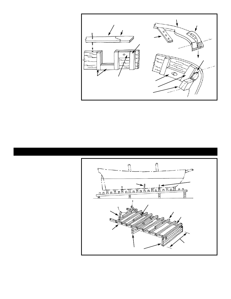
2. Launching Ways - A second type of
mounting that can be employed is the
launching ways, which are most suitable for
models without sails. Figure C-1 illustrates a
simple design. Drilling of the keel is still
required to insert rods that anchor the model
to the ways. The launching ways should be
mounted on a baseboard or could be placed
in a diorama comprised of boatyard ground
activity.
Baseboards, pedestals, and launching way
kits are available from Model Expo
(www.modelexpo-online.com).
STAGE C: MOUNTING THE HULL
FIG. B-5 BULWARK DETAILS
FIG. C-1 LAUNCHING WAY MOUNTING
ALIGNMENT
PIN OR NAIL
LASER-CUT RAIL
FORWARD
TYPICAL BULWARK
STANCHION
GUNPORT
FRAMING
DOUBLER IN
WAY OF SHEET
& TACK SHEAVE
HOLES
AFT SIDE OF
STEM PIECE
KNIGHTHEAD
HAWSE
TIMBER
LASER-CUT RAIL
RIGGING
FAIRLEAD
BLOCK
PIN
RAIL
CL
CL
CL
CL
BOWSPRIT
HOLE
STRIPWOOD RAIL AFT
WATERLINE
PARALLEL TO BASE
METAL ROD
OR WOOD
DOWEL
IN KEEL
BASE
KEEL BLOCKS
CROSS TIMBERS
SUPPORT
RAIL
SIDE SUPPORT
STRUTS
1/4" SQUARE
WOOD FOR
1/8" - 1/4" SCALE
MODELS
SUPPORT BLOCKS
HEIGHT SET SO MODEL WATERLINE
WILL BE PARALLEL TO BASE
SIDE SUPPORT
STRUTS P/S
ABOUT
1.5 X BEAM
OF HULL