3 protocol, Communication functions – MITSUBISHI ELECTRIC J2-JRSERIES MR-J2-03A5 User Manual
Page 161
13 - 5
13. COMMUNICATION FUNCTIONS
13.3 Protocol
Since up to 32 axes may be connected to the bus, add a station number to the command, data No., etc. to
determine the destination servo amplifier of data communication. Set the station number to each servo
amplifier using the parameter. Transmission data is valid for the servo amplifier of the specified station
number.
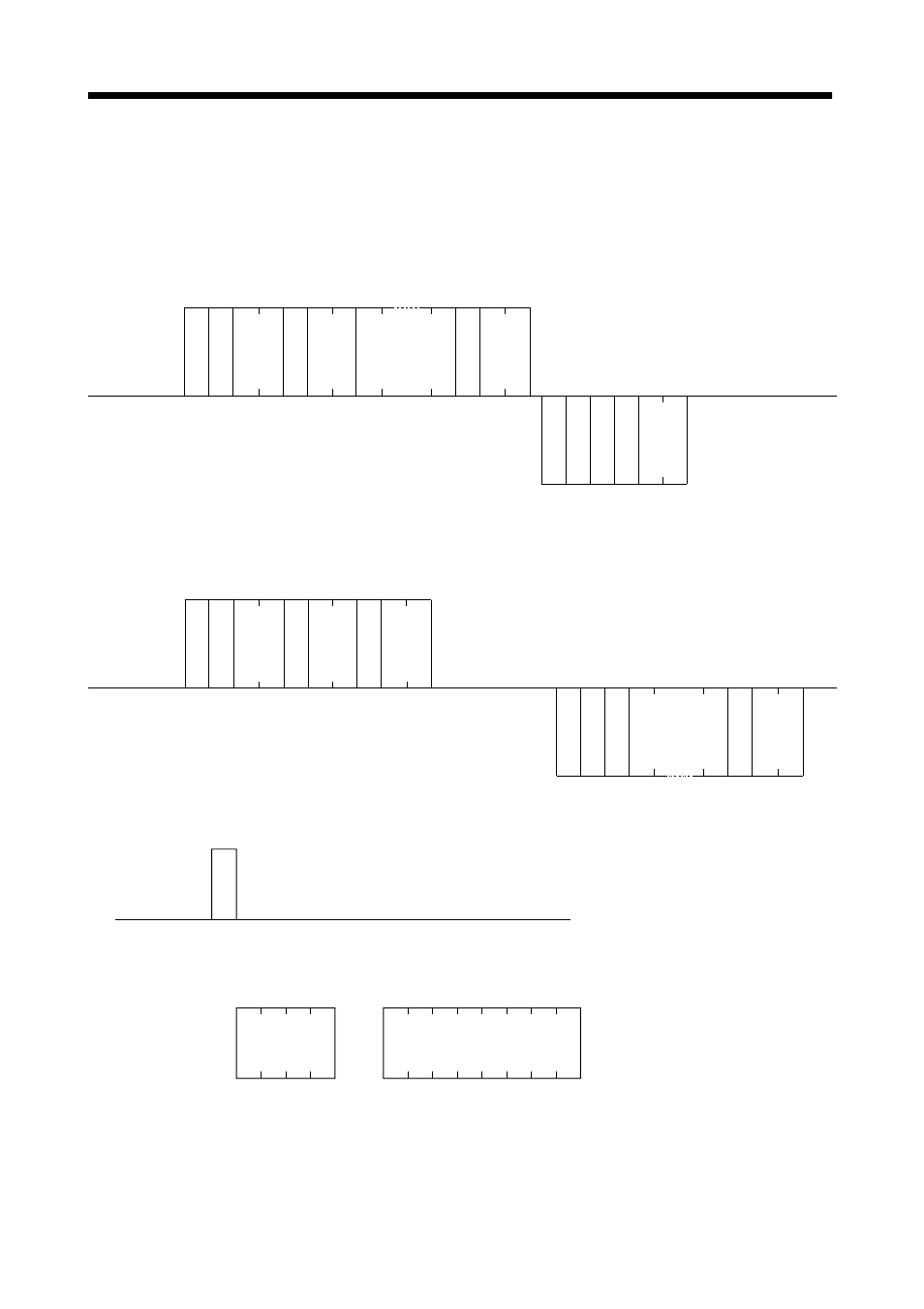
(1) Transmission of data from the controller to the servo
S
O
H
S
T
X
E
T
X
S
T
X
E
T
X
Data
No.
Data*
Check
sum
10 frames
+
(data)
E
rr
o
r code
Check
sum
6 frames
Positive response: Error code = A
Negative response: Error code = other than A
Servo side
(Slave station)
Controller side
(Master station)
C
o
mma
n
d
S
ta
ti
on num
b
e
r
S
ta
ti
on num
b
e
r
(2) Transmission of data request from the controller to the servo
S
O
H
S
T
X
E
T
X
S
T
X
E
T
X
Controller side
(Master station)
Servo side
(Slave station)
10 frames
C
o
mma
n
d
Data
No.
Check
sum
E
rr
o
r code
Data*
Check
sum
6 frames
+
(data)
S
ta
tio
n num
ber
S
ta
tio
n num
ber
(3) Recovery of communication status by time-out
E
O
T
or
Controller side
(Master station)
Servo side
(Slave station)
EOT causes the servo to return to
the receive neutral status.
Data
4 frames
Data
8 frames
or 12 frames or 16 frames
* Data: Choose the data length from among 4, 8, 12 and 16 frames (data length depends on the command).