Troubleshooting – MITSUBISHI ELECTRIC J2-JRSERIES MR-J2-03A5 User Manual
Page 132
9 - 8
9. TROUBLESHOOTING
Display
Name
Definition
Cause
Action
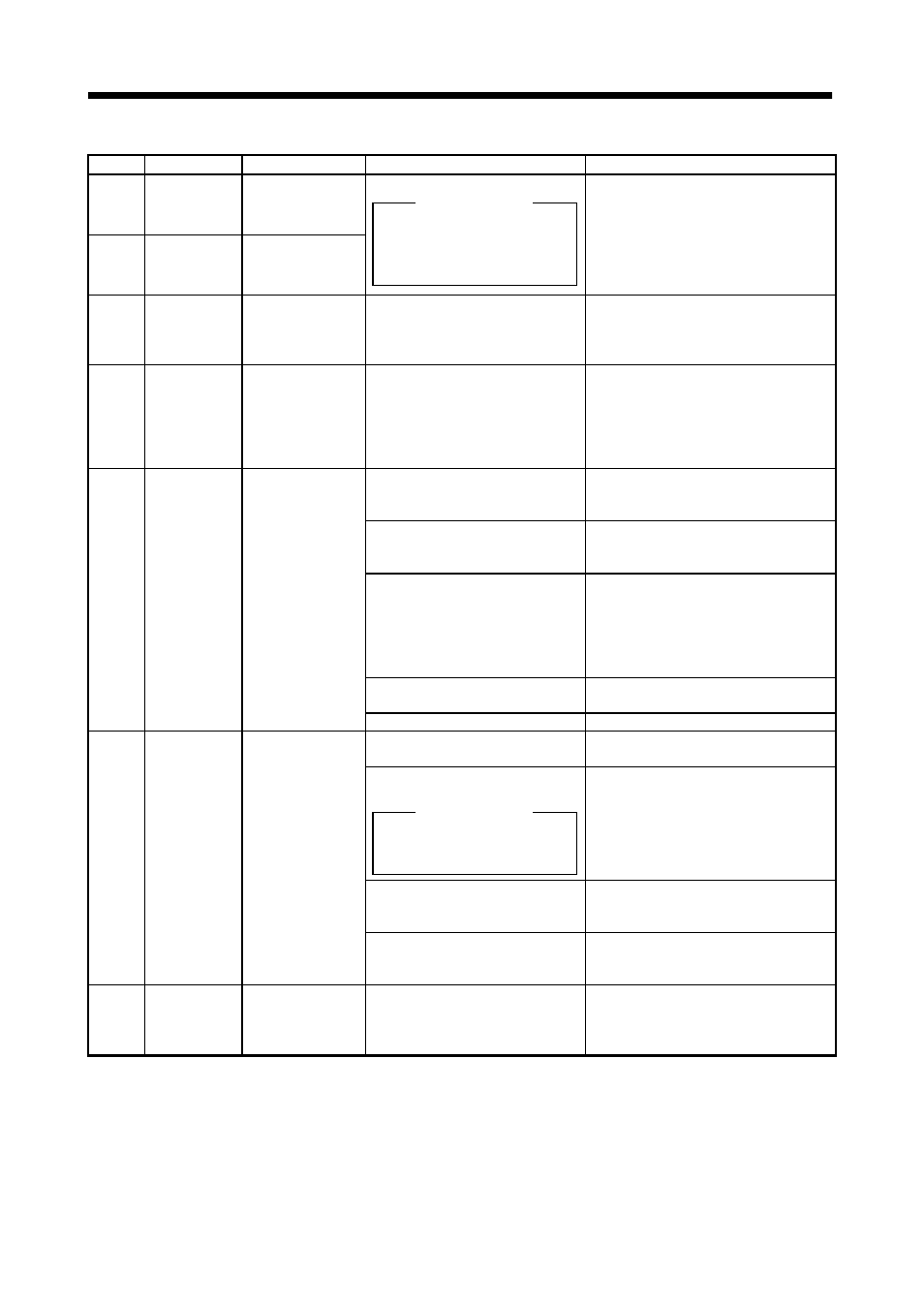
A. 17
Board error 2
CPU/parts fault
A. 18
Board error 3
Printed board fault
Faulty parts in the servo amplifier
Alarm (A. 17 or A. 18) occurs if
power is switched on after
connectors CN1A, CN1B,
CNP2, CNP3 are disconnected.
Checking method
Change the servo amplifier.
A. 20
Encoder error 2 Communication
error occurred
between encoder
and servo amplifier.
Motor cable faulty
(Encoder wiring broken or shorted)
Repair or change the cable.
A. 24
Motor outout
ground fault
Ground fault
occurred at the
servo motor outputs
(U,V and W phases)
of the servo
amplififer.
Servo motor power cable insulation
deteriorated.
Change the cable.
1. Input command pulse frequency
exceeded the permissible
instantaneous speed frequency.
Set command pulses correctly.
2. Small acceleration/deceleration
time constant caused overshoot to
be large.
Increase acceleration/deceleration time
constant.
3. Servo system is instable to cause
overshoot.
1. Re-set servo gain to proper value.
2. If servo gain cannot be set to proper
value:
1) Reduce load inertia moment ratio; or
2) Reexamine acceleration/
deceleration time constant.
4. Electronic gear ratio is large
(parameters No. 3, 4)
Set correctly.
A. 31
Overspeed
Speed has exceeded
the instantaneous
permissible speed.
5. Encoder faulty.
Change the servo motor.
1. Short occurred in servo amplifier
output phases U, V and W.
Correct the wiring.
2. Transistor (IPM) of the servo
amplifier faulty.
Alarm (A. 32) occurs if power is
switched on after U, V and W
are disconnected.
Checking method
Change the servo amplifier.
3. Ground fault occurred in servo
amplifier output phases U, V and
W.
Correct the wiring.
A. 32
Overcurrent
Current that flew is
higher than the
permissible current
of the servo
amplifier.
4. External noise caused the
overcurrent detection circuit to
misoperate.
Take noise suppression measures.
A. 33
Overvoltage
Input value of
converter bus
voltage reached or
exceeded 35V.
Power supply voltage is outside the
permissible voltage range.
Change battery.