MITSUBISHI ELECTRIC MSZ-FA35VA User Manual
Page 23
23
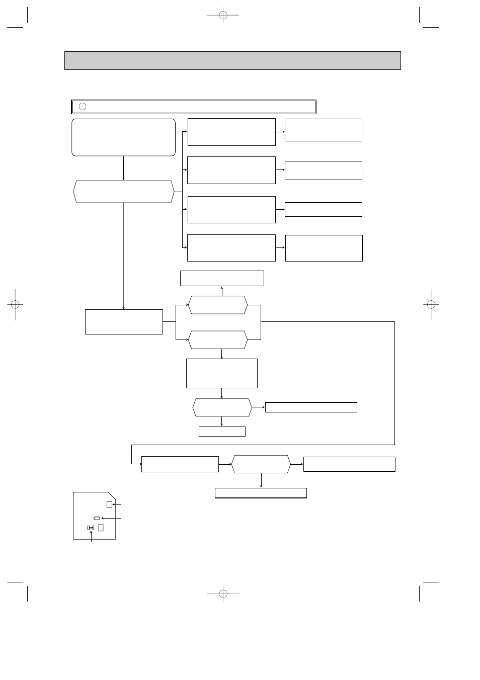
The unit does not operate with the remote controller.
Also, POWER lamp does not light up by pressing EMERGENCY OPERATION switch.
Check of indoor electronic control P.C. board and indoor fan motor
C
Yes
No
w
1. The fan motor connector's
1
lead wire is red, whereas
3
is black.
w
2. Connect "+" of the tester to fan motor connector's
1
lead
wire, and "-" to
3
lead wire, otherwise the resistance cannot be
measured properly.
w
3
w
3. Short circuit:
The indoor fan motor is
abnormal.
Yes
No
w
1,2
Does the unit operate with the remote controller?
Does POWER lamp light up by pressing EMERGENCY
OPERATION switch?
Turn OFF the power supply.
Remove indoor fan motor connector CN211, vane motor
connector CN151 front panel driving motor connector
connector CN1U1 and i-see Sensor motor connector
CN110 from the indoor electronic
control P.C. board and turn ON the power supply.
Measure the resistance of the horizontal vane
motor coil and the vertical vane motor coil.
Normal value is approx. 300
'
or 250
'
.
Measure the resistance between CN211
3
and
4
of the indoor fan motor connector.
Normal value is approx. 30k
'
to 50k
'
.
Short circuit:
Replace the indoor fan motor.
Short circuit:
Replace the horizontal vane motor, the
vertical vane motor and the indoor
electronic control P.C. board.
Turn OFF the power supply.
Check both “parts side” and “pattern
side” of the indoor electronic control P.C.
board visually.
Replace the varistor(NR11) and fuse(F11).
Are the varistor(NR11) burnt
and the fuse(F11) blown?
Be sure to check both the fuse
and the varistor in any case.
No
Yes
No
Is the fuse(F11) blown only?
Yes
No
Is the resistance 1M
'
or more?
Measure the resistance between
1
(+) and
3
(-) of the indoor fan
motor connector (to CN211 on the
indoor electronic control P.C. board) .
Replace the fuse (F11).
Replace the fuse (F11) and the indoor fan motor.
Is the resistance
approx. 4
'
?
Measure the cement resistance R111 on
the indoor electronic control P.C. board.
Replace the indoor electronic control P.C. board.
Replace the indoor electronic control P.C. board
and the indoor fan motor.
Yes
Measure the resistance of i-see Sensor
motor coil.
Normal value is approx. 300
'
Measure the resistance of the front panel
driving motor coil.
Normal value is approx. 100
'
Short circuit:
Replace the front panel driving motor
and the indoor electronic control P.C.
board.
Short circuit:
Replace i-see Sensor motor and the
indoor electronic control P.C. board.
CN211
Fuse(F11)
Varistor(NR11)
CN201
Indoor electronic
control P.C.Board
OB371_--1qxp 05.1.17 12:50 Page 23