Mvp210ss circuit board, Ch1 ch2, Ch 2 jumper block – Multi-Tech Systems MVP210-SS User Manual
Page 74: Ch 1 jumper block
Mechanical Installation & Cabling
MultiVOIP User Guide
74
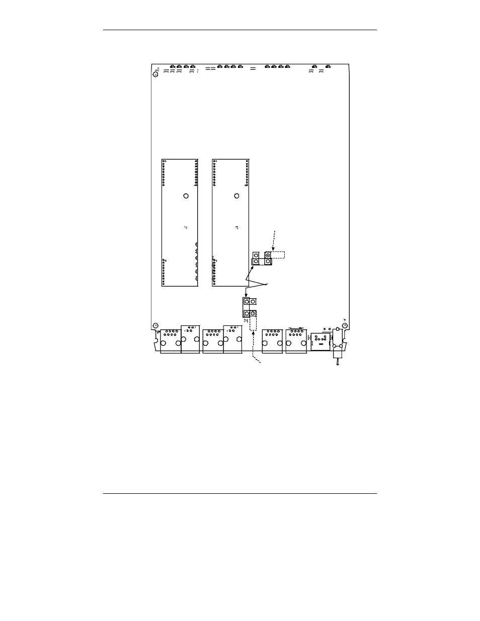
d. Identify the channels on which the DID interface will be used.
J3
J 7
J9
J5
J 11
F B 3
L E D2
R7 2
J1
S 1 0
R 113
R114
L E D1 2
J 15
L E D7
L E D11
L E D10
L E D1 4
LE D5
LE D3
L E D1
R58
R2
R 57
L ED6
LE D4
LE D9
R56
R 74
R2 05
L ED1 3
R5 5
LE D8
Ch1
Ch2
Ch 2 Jumper
Block
MVP210SS Circuit Board
JP1
JP8
as configured
for DID Interface
as shipped,
for non-DID interfaces
Ch 1 Jumper
Block
JP7
JP4
as configured
for DID Interface
P7
Figure 3-10. MVP210-SS Channel Jumper Settings
e. Position the jumper for each DID channel so that it does not connect
the two jumper posts. For DID operation of a voip channel, the
MultiVOIP will work properly if you simply remove the jumper
altogether, but that is inadviseable because the jumper might be
needed later if a different telephony interface is used for that voip
channel.
f. Slide the main circuit card back into the MultiVOIP chassis and
replace the screw at the bottom of the unit.