6 subsystem configuration, Dual drive support, Cable select option – Maxtor D540X-4G User Manual
Page 18: Figure 2-1 pcba jumper location and configuration, 6 subsystem configuration -6, Figure 2-1, Pcba jumper location and configuration -6
Product Description
2-6
Maxtor D540X-4G
5WDU[UVGO %QPHKIWTCVKQP
&WCN &TKXG 5WRRQTV
Two drives may be accessed via a common interface cable, using the same range of
I/O addresses. The drives have a jumper configuration as device 0 or 1 (Master/
Slave), and are selected by the drive select bit in the Device/Head register of the
task file.
All Task File registers are written in parallel to both drives. The interface processor
on each drive decides whether a command written to it should be executed; this
depends on the type of command and which drive is selected. Only the drive
selected executes the command and activates the data bus in response to host I/O
reads; the drive not selected remains inactive.
A master/slave relationship exists between the two drives: device 0 is the master and
device 1 the slave. When the Master is closed (factory default, figure 2-1), the drive
assumes the role of master; when open, the drive acts as a slave. In single drive
configurations, the Master jumper must be closed.
%CDNG 5GNGEV 1RVKQP
CSEL (cable select) is an optional feature per ANSI ATA specification. Drives
configured in a multiple drive system are identified by CSEL’s value:
– If CSEL is grounded, then the drive address is 0.
– If CSEL is open, then the drive address is 1.
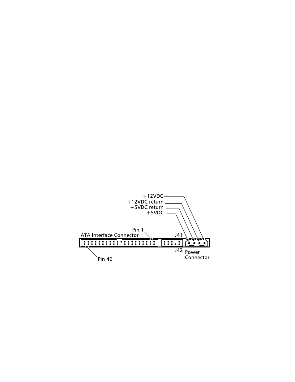
Figure 2-1
PCBA Jumper Location and Configuration