Installation – MGE UPS Systems 30A User Manual
Page 14
Page 14 -
34020113EN/AA
N
PEN
N
PE
PEN
S1
S2
N L1 L2 L3
N L1 L2 L3
N L1 L2 L3
N
PEN
PEN
PEN
S1
S2
N L1 L2 L3
N L1 L2 L3
N L1 L2 L3
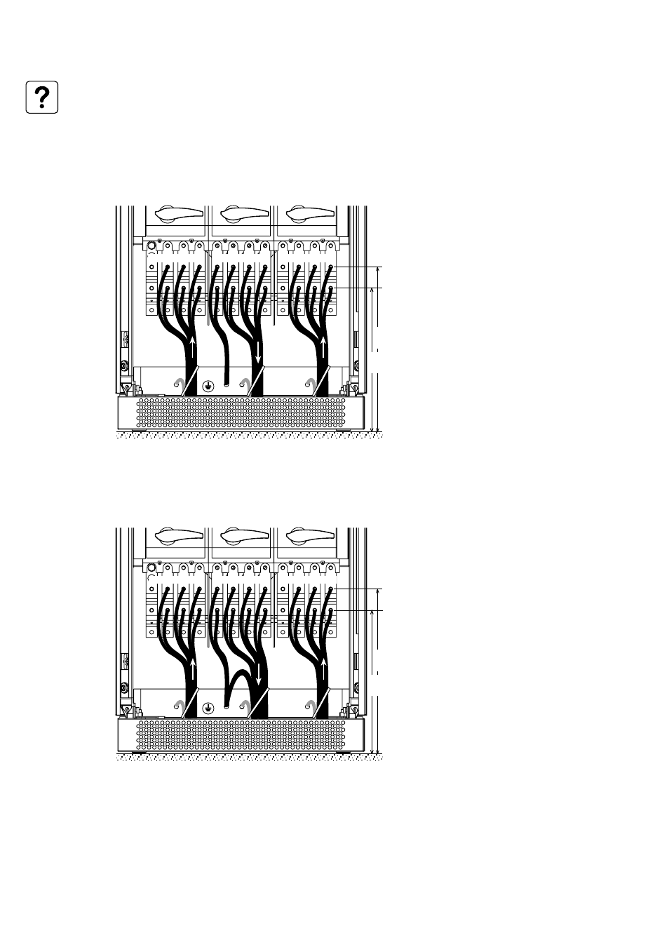
Upsilon STS 400 to 600 A
Input:
3 phases + PEN
Output:
3 phases + PEN
See section 1.3 for information on accessing
the connections.
Connections are made using lugs connected
to two threaded studs per phase (diameter
10 mm).
The cables are tied to the earth bar.
2. Installation
463
mm
403
mm
See section 6.1 for information on sizing protection devices and cables (Appendix, Technical data).
A maximum of four cables may be used per phase.
Upsilon STS 400 to 600 A
Input:
3 phases + PEN
Output:
3 phases + PE + Neutral
See section 1.3 for information on accessing
the connections.
Connections are made using lugs connected
to two threaded studs per phase (diameter
10 mm).
The cables are tied to the earth bar.
463
mm
403
mm
- Pulsar EX 1000 (28 pages)
- 4.5 kVA (32 pages)
- 1100 (196 pages)
- EPS 8000 (54 pages)
- S EXB 2500 (22 pages)
- Pulsar Extreme 3200C (28 pages)
- ESV 22+Rack (24 pages)
- GES-801L (22 pages)
- Comet EX 7 RT 3:1 (38 pages)
- EX 11RT (72 pages)
- Galaxy PW (44 pages)
- 3 (34 pages)
- Pulsar TM 30 (18 pages)
- 22+ EB 22 (44 pages)
- 1500C (28 pages)
- Rackmount PDU (36 pages)
- Pulsar Esprit 313.5 kVA (6 pages)
- EX-5 (76 pages)
- AmpMeter PDU (52 pages)
- EX30 (106 pages)
- 1100 Tower (36 pages)
- 40-75KVA (56 pages)
- 2000 (34 pages)
- 4000 RT (38 pages)
- Pulsar EXtreme C UPS 1500 VA (4 pages)
- FlexPDU 6 AUS (12 pages)
- POWER-SURE 700 (52 pages)
- 250A (34 pages)
- EX 1000 (28 pages)
- EX7 (18 pages)
- EX30Rack (24 pages)
- 12280 kVA (13 pages)
- 40-150kVA (56 pages)
- 100 (32 pages)
- Uninterruptible Power Provider (4 pages)
- EPS 7000 (62 pages)
- 300 (6 pages)
- EX10Rack (22 pages)
- 500 (4 pages)
- EPS 6000 (84 pages)
- S3 (64 pages)
- EX RT CLA (6 pages)
- 3000 (32 pages)
- 3.5 to 21 kVA N+1 (54 pages)