Installation – MGE UPS Systems 30A User Manual
Page 13
34020113EN/AA
- Page 13
PEN
N
PE
PEN
S1
S2
N L1 L2 L3
N L1 L2 L3 N L1 L2 L3
PE
N
PE
PE
N
N
S1
S2
N L1 L2 L3
N L1 L2 L3 N L1 L2 L3
PE
PE
PE
S1
S2
N L1 L2 L3
N L1 L2 L3 N L1 L2 L3
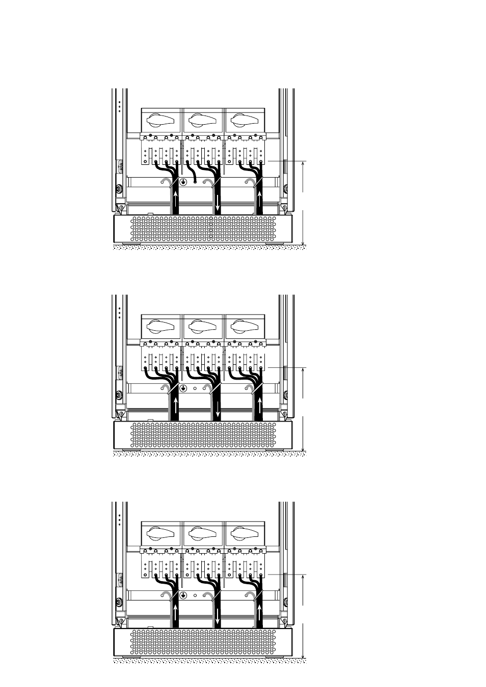
2. Installation
See section 1.3 for information on accessing
the connections.
Connections are made using lugs connected
to threaded studs (diameter 8 mm).
The cables are tied to the earth bar.
See section 1.3 for information on accessing
the connections.
Connections are made using lugs connected
to threaded studs (diameter 8 mm).
The cables are tied to the earth bar.
Upsilon STS 30 to 250 A
Input:
3 phases + PE + Neutral
Output:
3 phases + PE + Neutral
275 mm
275 mm
See section 1.3 for information on accessing
the connections.
Connections are made using lugs connected
to threaded studs (diameter 8 mm).
The cables are tied to the earth bar.
275 mm
Upsilon STS 30 to 250 A
Input:
3 phases + PEN
Output:
3 phases + PE
Upsilon STS 30 to 250 A
Input:
3 phases + PE
Output:
3 phases + PE
- Pulsar EX 1000 (28 pages)
- 4.5 kVA (32 pages)
- 1100 (196 pages)
- EPS 8000 (54 pages)
- S EXB 2500 (22 pages)
- Pulsar Extreme 3200C (28 pages)
- ESV 22+Rack (24 pages)
- GES-801L (22 pages)
- Comet EX 7 RT 3:1 (38 pages)
- EX 11RT (72 pages)
- Galaxy PW (44 pages)
- 3 (34 pages)
- Pulsar TM 30 (18 pages)
- 22+ EB 22 (44 pages)
- 1500C (28 pages)
- Rackmount PDU (36 pages)
- Pulsar Esprit 313.5 kVA (6 pages)
- EX-5 (76 pages)
- AmpMeter PDU (52 pages)
- EX30 (106 pages)
- 1100 Tower (36 pages)
- 40-75KVA (56 pages)
- 2000 (34 pages)
- 4000 RT (38 pages)
- Pulsar EXtreme C UPS 1500 VA (4 pages)
- FlexPDU 6 AUS (12 pages)
- POWER-SURE 700 (52 pages)
- 250A (34 pages)
- EX 1000 (28 pages)
- EX7 (18 pages)
- EX30Rack (24 pages)
- 12280 kVA (13 pages)
- 40-150kVA (56 pages)
- 100 (32 pages)
- Uninterruptible Power Provider (4 pages)
- EPS 7000 (62 pages)
- 300 (6 pages)
- EX10Rack (22 pages)
- 500 (4 pages)
- EPS 6000 (84 pages)
- S3 (64 pages)
- EX RT CLA (6 pages)
- 3000 (32 pages)
- 3.5 to 21 kVA N+1 (54 pages)