Meade Instruments RCX400 User Manual
Page 72
72
Note: Tightening to a firm-feel is sufficient. Over-tightening may result in
stripping of the knob threads or damage to the tripod legs; it provides no
additional strength.
Loosen the tension knob (
3, Fig. 58), holding the spreader bar (4, Fig. 58), and slide
the spreader bar down the threaded rod until you can rotated it so that the three arms
align with the three tripod legs. Tighten the tension knob (
Fig. 60) to a firm feel; firm
tightening of the tension knob is sufficient to result in rigid positioning of the legs.
Do
not use force in tightening this knob.
To collapse the tripod (after removing the telescope) for storage, follow these
steps:
a. Loosen the tension knob and rotate the spreader bar 60° from its assembled posi-
tion, so that one spreader bar arm is located between each adjacent pair of tripod
legs.
b. Move the spreader bar to the top of the threaded rod. Tighten the tension knob, lock-
ing the bar.
c. Working one leg at a time, gradually collapse the legs of the field tripod until the ten-
sion hub is positioned onto the threaded rod. Use the second tension knob to
secure the tension hub in place.
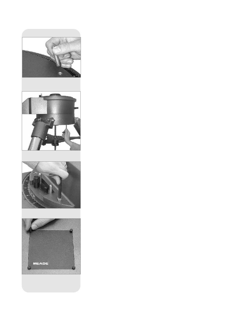
Attaching the 16” Drive Base
a. Remove the three pointed bolts that hold the packing material in place. These bolts
are used only for shipping purposes and not used in the telescope assembly pro-
cedure. See
Fig. 61.
b. Rotate the field tripod so that one leg is pointing approximately South (it need not
point exactly South).
c. Position the 16” drive base onto the field tripod, with the power panel facing South.
Secure the drive base using the three 1/2”-13x1-1/2” long bolts. Thread these bolts
up through the underside of the tripod head into the drive base using the supplied
hex key. Firmly tighten these bolts. See
Fig. 62.
c. Level the drive base by loosening the six lock-knobs (
5, Fig. 58) and sliding out the
inner tripod legs.
d. Note the DB-15 connector at the center of the base.
Attaching the Fork
a. Place the single-piece fork onto the top of the drive base. One side of the base of
the fork has a cutout to allow clearance for the R.A. lock (
13, Fig. 1) and R.A. slow-
motion control (
8, Fig. 1), which are located on top of the drive base.
b. Bolt the fork to the drive base using the four 3/8”-16x3/4” long bolts (
Fig. 63). Using
the supplied hex key, tighten to a firm feel only.
c. Unscrew and remove the four thumbscrews from the rectangular plate (
Fig. 64) in
the center of the fork base. Remove the plate. Note the DB-37 plug under the fork
base.
d. Connect the DB-37 plug to the DB-37 connector underneath the plate. Tighten the
two thumbscrews onto the connector to a firm feel. See
Fig. 65.
e. A fifth 3/8”-16x3/4” long bolt is supplied with the telescope. Just using your fingers,
loosely tighten this bolt under the plate. See
Fig. 65. This bolt acts as a safety fea-
ture to prevent the DB-37 connector and cable from being damaged when you dis-
assemble the telescope. You will not be able to disassemble the telescope until the
bolt is removed. The bolt is located near the DB-37 assembly in the base as a
reminder to unplug the connector before removing the fork from the drive base.
Mounting the Optical Tube Assembly (OTA)
This step requires two people who can lift up to 90 pounds each (
Note: See Caution
in the margin on page 71. The optical tube assembly (OTA) weighs about 145 lbs. and
it must be positioned accurately in order to mount to the fork.
Fig. 62: Attach the drive base to the
tripod.
Fig. 63 Bolt the fork to the drive base.
Fig. 64: Remove the four thumb-
screws from the plate.
7 2
Fig. 61: Remove the pointed bolts
from the drive base.