Section 5 − installation, 1. installing welding generator, 2. grounding generator to truck or trailer frame – Miller Electric BLUE STAR 145 DX User Manual
Page 17
OM-4417 Page 13
SECTION 5 − INSTALLATION
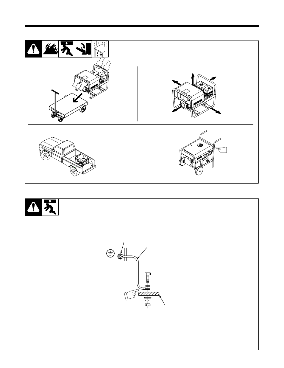
5-1. Installing Welding Generator
Ref 151 556 / Ref. 800 652 / 803 594-B / S-0854
18 in
(460 mm)
18 in
(460 mm)
18 in
(460 mm)
18 in
(460 mm)
18 in
(460 mm)
OR
Movement
Airflow Clearance
Location
Shown with
optional
running gear.
Y Always securely fasten welding generator
onto transport vehicle or trailer and comply
with all DOT and other applicable codes.
5-2. Grounding Generator To Truck Or Trailer Frame
install1 11/02* − Ref. 151 556 / S-0854
Y Always ground generator
frame to vehicle frame to pre-
vent electric shock and static
electricity hazards.
1
Metal Vehicle Frame
2
Equipment Grounding
Terminal
3
Grounding Cable
Use #10 AWG or larger insulated
copper wire.
Y If unit does not have GFCI
receptacles, use GFCI-
protected extension cord.
Electrically bond generator frame
to vehicle frame by metal-to-metal
contact.
GND/PE
2
3
1
Y Bed liners, shipping skids, and some running
gear insulate the welding generator from the ve-
hicle frame. Always connect a ground wire from
the generator equipment grounding terminal to
bare metal on the vehicle frame as shown.