Warning, 2 - safety precautions 3 - assembly instructions – McCulloch 9096336202 User Manual
Page 4
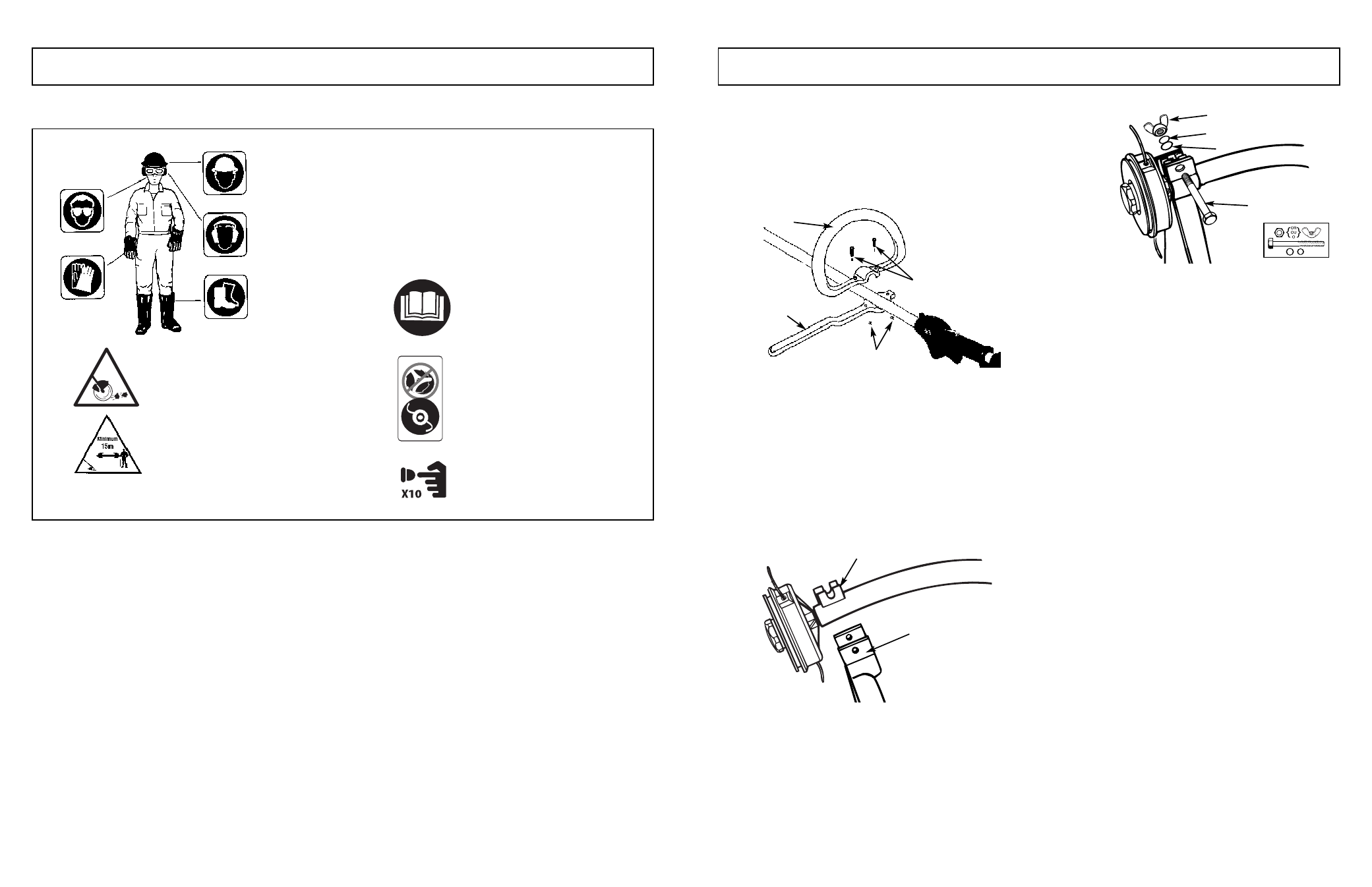
3-1. “P” HANDLE ASSEMBLY
1.
To install handle onto unit, you will need the following
components from your user kit: “P” handle (A & B),
screws (C) and nuts (D). (Figure 3-1).
2.
Install the handle (B) on the shaft
6.0” to 7.87”
(160-
200mm) from throttle and tighten the 2 screws (C) and
nuts (D).
3-2. DEBRIS SHIELD
WARNING
The debris shield must be installed (Figure 3-2A) to prop-
erly dispense cutter line and protect operator.
Shield fits snug on shaft. Some force may be required.
1.
Seat shield (A) onto shaft bracket (B). (Fig. 3-2A)
2.
Insert bolt (C), washer (D), lock washer (E) and wing
nut (F), tighten securely. (Fig. 3-2B)
6
7
2 - SAFETY PRECAUTIONS
3 - ASSEMBLY INSTRUCTIONS
Use of these personal safety items is highly recommended to
reduce the risk of accidental injury.
Minimum operating distance
2-3. INTERNATIONAL SYMBOLS
Do not use blade on this unit.
Read the User Manual.
Pump the primer bulb 10 times.
3-1A
A
B
C
D
3-2A
B
3-2B
F
A
E
D
C