Installation, Output on the rear panel of the system – Maxtor 16 Channel Digital Video Recorder User Manual
Page 7
Installation
Procedure
7
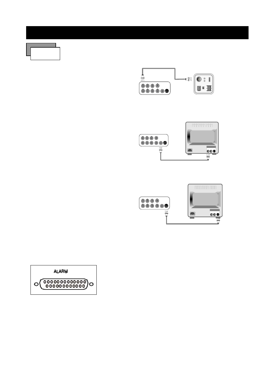
1) Camera Connection
Connect the camera to the CAMERA INPUT
on the Rear Panel of the 16 CH DVR.
CH1
CH2
CH3
CH4
CH1
CH2
CH3
CH4
MONITOR
VIDEO
LENS
VIDEO
DC
AC24V/DC12
V.P
DC
LEVEL
Rear part of CAMERA
2) Monitor Connection (Composite Connection
Method)
Connect the monitor to the MONITOR OUT on
the Rear Panel of the 16 CH DVR.
CH1
CH2
CH3
CH4
CH1
CH2
CH3
CH4
MONITOR
VIDEO A
IN
OUT
3) Monitor Connection
Connect S-VIDEO Monitor to MONITOR OUT
on the Rear Panel of the 16 CH DVR.
CH1
CH2
CH3
CH4
CH1
CH2
CH3
CH4
MONITOR
VIDEO A
IN
OUT
4) Sensor Connection
Connect the Sensor to the SENSOR INPUT/
1. ALARM 1 14. ALARM 13
2. ALARM 2 15. ALARM 14
3. ALARM 3 16. ALARM 15
4. ALARM 4 17. ALARM 16
5. ALARM 5 18.
6. ALARM 6 19.
7. ALARM 7 20. DGND
8. ALARM 8 21. ALARM COM
9. ALARM 9 22. ALARM NC
10.ALARM 10 23. ALARM NO
11. ALARM 11 24. DGND
12.ALARM 12 25. DGND
13. DGND
OUTPUT on the Rear Panel of the system
13,12,11,10,9,8,7,6,5,4,3,2,1
25,24,23,22,21,20,19,18,17,16,15,14
◆Relay output : COM+NC, COM+NO
◆Alarm input : Short-circuit between Alarm1, Alarm2, Alarm3 or Alarm4 and GND is recognized as alarm
by default. Alarm 1 ~ 16 will be corresponding to Camera 1 ~ 16.