Rear panel, Names and functions of parts, A phono input jacks – Marantz PM7001 User Manual
Page 12: B phono gnd terminal, C pre out jacks, D main in jacks, E speakers system 1, 2 output terminals, F ac in socket, G remote control jacks, I recorder 1/recorder 2 output jacks
7
ENGLISH
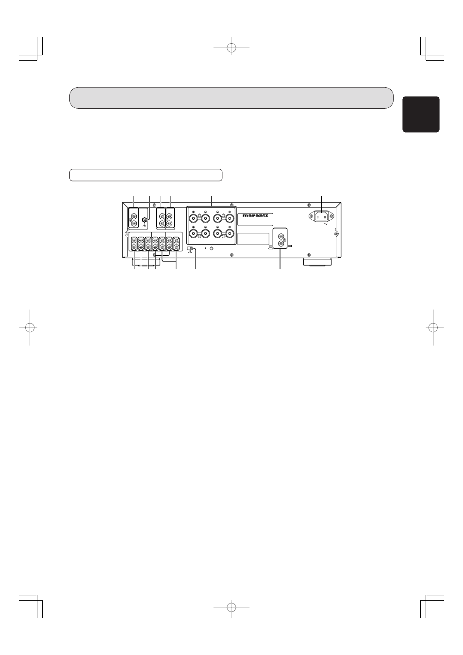
REAR PANEL
NAMES AND FUNCTIONS OF PARTS
A PHONO Input jacks
These jacks are for connecting to an analog record player.
MM cartridges can be used.
B PHONO GND terminal
Connect the grounding wire from an analog record player.
C PRE OUT jacks
These jacks are for connecting to the input jacks of an-
other main-amplifier or active subwoofer.
D MAIN IN jacks
These jacks are for connecting to the output terminals of
another pre-amplifier when using the PM7001 as the main-
amplifier. In this case, set the SEPARATE switch H to the
ON position.
E SPEAKERS SYSTEM 1, 2 output terminals
You can connect 2 speaker systems, SPEAKERS 1 and
SPEAKERS 2 E. Speaker output can be turned ON/OFF
from the SPEAKERS 1 and 2 buttons o on the front panel.
F AC IN socket
Connect the supplied AC power cable to this socket and a
power outlet.
G REMOTE CONTROL jacks
These jacks are for connecting to other Marantz
components such as a CD player or DVD player that has a
remote control connector (D.BUS jack).
You can use the remote controller supplied with the PM7001
to control the system.
For more details, see page 13.
MODEL NO. PM7001
L
L
SYSTEM 1 OR SYSTEM 2 4
SYSTEM 1 OR SYSTEM 2 4 -
-16 OHMS
16 OHMS
SYSTEM 1 AND SYSTEM 2 8
SYSTEM 1 AND SYSTEM 2 8 -
-16 OHMS
16 OHMS
SPEAKERS
SPEAKERS
R
R
L
L
MAIN IN
MAIN IN
L
L
R
R
PRE OUT
PRE OUT
GND
GND
R
R
L
L
CD
CD
AUX
AUX
// DVD
DVD
TUNER
TUNER
OUT
OUT
IN
IN
RECORDER 1
RECORDER 1
OUT
OUT
IN
IN
RECORDER 2
RECORDER 2
AC IN
AC IN
R
R
L
L
R
R
OFF
OFF
SEPARATE
SEPARATE
OUT
OUT
IN
IN
REMOTE
REMOTE
CONTROL
CONTROL
SERIAL NO.
SERIAL NO.
PHONO
PHONO
ON
ON
R
L
SYSTEM 1
SYSTEM 2
A
C D
E
F
G
H
I
J
K
L
M
B
H SEPARATE switch
This switch is used for selecting the pre-amplifier and main-
amplifier connection modes.
OFF: Select this position when the amplifier is used as a
normal integrated amplifier. (Standard factory set-
ting)
ON:
The pre-amplifier and main-amplifier are separated.
The PM7001 can be used as a main-amplifier when
input is connected to the MAIN IN jacks D.
I RECORDER 1/RECORDER 2 output jacks
These jacks are for connecting to the recording input jacks
of a CD-R recorder, MD deck, tape deck, etc. Output sig-
nals can be selected using the REC SELECTOR knob !2
on the front panel.
J RECORDER 1/RECORDER 2 input jacks
These jacks are for connecting to the output jacks of a CD-
R player, MD deck, tape deck, etc.
K AUX/DVD input jacks
These jacks are for connecting to the output jacks of a
DVD player or other LINE component.
L TUNER input jacks
These jacks are for connecting to the output jacks of a
tuner or other LINE component.
M CD input jacks
These jacks are for connecting to the output jacks of a CD
player or similar component.
!3 Infrared Receptor Window
This is the receptor of control signals sent from the
RC4001PM remote controller. Point the remote controller
towards this window to properly transmit signals.
!4 PHONES jack
This jack is for connecting headphones with a standard
stereo plug. To listen with headphones, turn the speaker
output OFF by setting the SPEAKERS 1 and 2 buttons o
in the OFF position.
05.7.20, 3:46 PM
Page 7