Control panel components, Figure 8. digital control panel components – Multiquip Control Box Replacement LS60TD User Manual
Page 6
LS60TD anD LS600 — COnTROL bOX RepLaCemenT — Rev. #1 (03/23/12) — page 6
COnTROL paneL COmpOnenTS
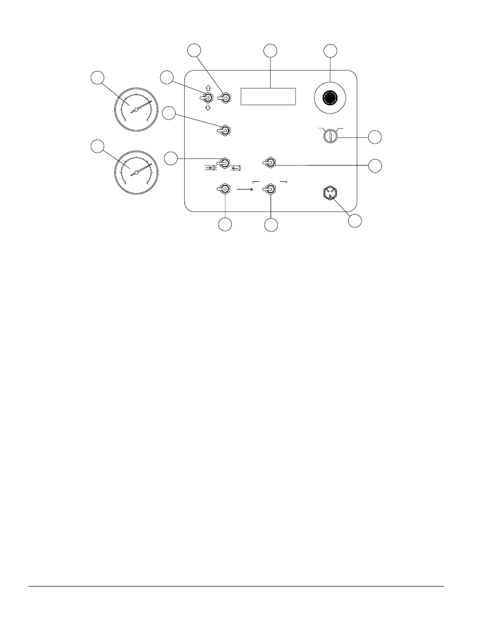
Figure 8. Digital Control Panel Components
0
5
0
0
7
5
0
1000
12
5
0
1
5
0
0
2
0
0
0
0
5
0
0
7
5
0
1000
12
5
0
1
5
0
0
2
0
0
0
E
M
E
RG
ENCY S
TO
P
ACCUMULATOR
PRESSURE
PUMPING
PRESSURE
1
2
4
5
6
10
9
7
3
8
12
11
13
OFF
ON
IGNITION
REMOTE
CONTROL
FLOW
DIRECTION
VOLUME
LOCAL
FORWARD
AUTOMATIC
JOG
RESET
SET
DECREASE
INCREASE
SCROLL
JOG “A”
CYLINDER STROKE
JOG “B”
REVERSE
CENTER
OFF
REMOTE
START
1.
emergency Stop button —Pressemergencystop
button to stop pump in an emergency.Turn knob
counterclockwisetodisengagethestopbutton.
2.
ignition Switch —Inserttheignitionkeyheretostart
theengine.TurnthekeyclockwisetotheONposition,
thencontinueturningclockwisetotheSTARTposition
and release.To stop the engine turn the key fully
counterclockwisetotheSTOPposition.
3.
Digital Readout Screen —Displaysandmonitorsthe
variousfunctionsofthemachine.
4.
Scroll Switch — Allows the operator to scroll the
variousreadoutscreens.
5.
Reset Switch — Allows the operator to reset the
strokecounter.
6.
Remote Cable Connector —Inserttheremotecontrol
inputcableintothisconnector.
7.
Direction Control Switch —This2-positionswitch
controlsthedirectionofflowforanymixinthepump.
The leftmost position sets the pumping direction to
forwardandtherightmostpositionsetsthepumping
directiontoreverse.
8.
pumping Control Switch —This3-positionswitch
controls the pumping of the pump.The rightmost
position(REMOTE)isforusewiththeremotecontrol
unit, the leftmost position (LOCAL) is for normal
pumping operation, and the centermost position
(CENTEROFF)preventspumping.
9.
Cylinder Stroke Control Switch —This2-position
switch controls the pumping function.The leftmost
position (AUTOMATIC) sets the pump to automatic
cycling.Settheswitchtothispositionfornormalpump
operation.
Therightmostposition(JOG)changesthepumpfrom
automatictomanualcycling.Thisallowsthecylinders
to be manually cycled using the Manual Cylinder
JoggingSwitch.
10.
manual Cylinder Jogging Switch —This2-position
switchallowstheoperatortomanuallyjogthecylinders
toassistinclearingmateriallinepacksandisusedto
testpumpingpressure.
The leftmost position jogs Cylinder “A” and the
rightmostpositionjogsCylinder“B”.
11.
Stroke volume Control Switch — Increases or
decreasesthenumberofstrokesperminuteofthe
pump(notusedonmodelLS60TD).
12.
accumulator pressure gauge — This gauge
monitorstheinternalpressureoftheAccumulatortank.
Normalinternalpressureshouldreadapproximately
1750PSIduringpumping.
13.
main pressure gauge —This gauge monitors
the system pressure while pumping material.The
maximumpressureratingis4400PSI±50.