Cabling your multifrad 3000, 15 chapter 2 - installation – Multitech MULTIFRAD 3100 User Manual
Page 15
15
Chapter 2 - Installation
Cabling your MultiFRAD 3000
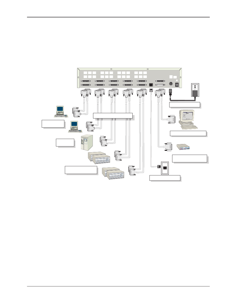
Cabling your MultiFRAD involves making the proper Power, Command Port, Ethernet, and Channel
connections. Figure 3 shows the back panel connectors and the associated cable connections. The
MF3060 supports up to 6 data channels and the MF3100 supports up to 10 data channels. The MF
3060 cannot be upgraded to support 10 channels. Table 1 details the procedures for connecting the
cables to your MultiFRAD.
E&M
FXO
FXS
E&M
FXO
FXS
E&M
FXO
FXS
E&M
FXO
FXS
VOICE/
FAX
CHANNEL
8
VOICE/
FAX
CHANNEL
4
VOICE/
FAX
CHANNEL
7
VOICE/
FAX
CHANNEL
3
VOICE/
FAX
CHANNEL
6
VOICE/
FAX
CHANNEL
2
VOICE/
FAX
CHANNEL
5
VOICE/
FAX
CHANNEL
1
CHANNEL 10
CHANNEL 9
CHANNEL 8
CHANNEL 7
CHANNEL 6
CHANNEL 5
CHANNEL 4
CHANNEL 3
CHANNEL 2 (RS232/V.35)
CHANNEL 1 (RS232/V.35)
10BASET
ETHERNET
COMMAND PORT
EXT. COMPOSITE LINK (RS232/V.35)
POWER
I
O
GND
T1 DSU
MONITOR
XMT RCV
INTERNAL
COMPOSITE
LINK
Channel Connections
Power Connection
Statistical Multiplexers
Ethernet Connection
Command Port Connection
T1 CSU/DSU or Comparable
Link Device
PC or
Terminal Units
AS400
TM
Figure 3. Cable Connections
Table 1. Cabling Procedure
Step
Procedure
1
Connect one end of an DB-25 cable to each of the data channel connectors on the back of
your MultiFRAD (labeled CHANNEL 1-6 for the MF3060, CHANNEL 1-10 for the MF3100).
See Figure 3. Connect the other end of each cable to the channel devices. Repeat for each
of the up to 6 or 10 channels you are connecting.
NOTE: only Channels 1 and 2 support the RS232/V.35 protocol, and all channels support
either asynchronous or HDLC synchronous RS232 data equipment such as multiplexers.
2
Connect one end of an DB-25 (female) cable to the Ext. Composite Link Connector on the
back of the MultiFRAD (as shown in Figure 3). Connect the other cable end to your T1 CSU/
DSU or compatible link device.
3
If you have a LAN, make the network connection by connecting a RJ-45 (UTP) cable to the
10 BASE-T Ethernet connector (shown in Figure 3) on the back of the MultiFRAD. Connect
the other end of the cable to your LAN.