Typical wiring diagram shd-30 model dimensions, Shd-30-45 model dimensions, How to order – Murphy Digital Tach/Hourmeter with Overspeed Trip Point SHD30-45 User Manual
Page 2: Specify model number, Backup battery (2 required), Warranty, Front view side view, Mounting hole, Or magnetic switches is the n.o. scr, Warning
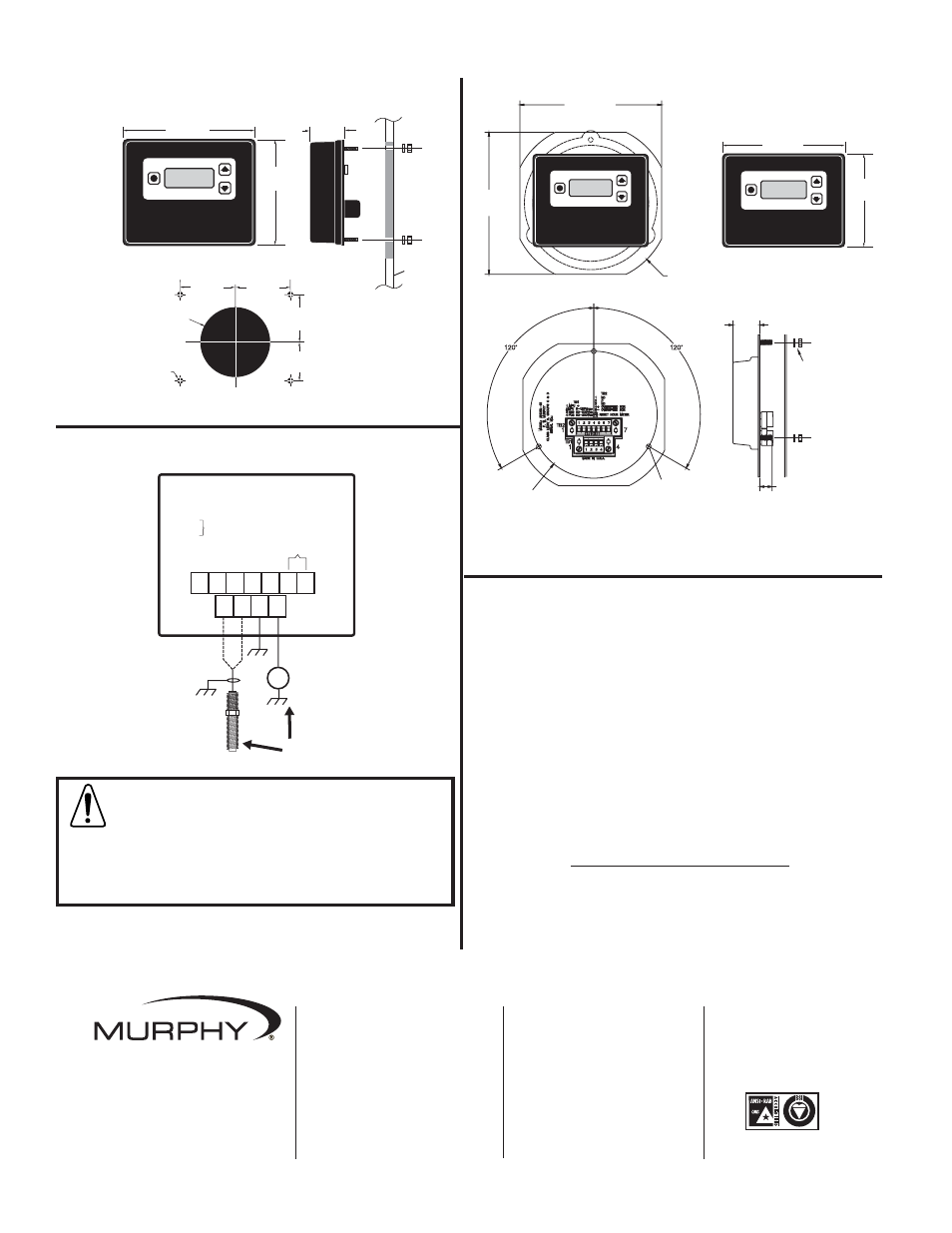
Typical Wiring Diagram
SHD-30 Model Dimensions
Front View Side View
SHD-30-45 Model Dimensions
panel
4-1/4 in.
(108 mm)
5-1/16 in.
(129 mm)
1-9/32 in.
(33 mm)
2 in.
(51 mm)
2 in.
(51 mm)
1-1/2 in.
(38 mm)
2 in.
(51 mm)
3/16 in
(5 mm)
diameter,
4 places
3-1/8 in.
(79 mm)
diameter
CD Ignition
90-350VDC
+
—
5-120Vrms
IGN
Shield
ground
Magnetic Pickup
5 - 120Vrms
OR
C. N.C.
+
+
–
–
N.O.
1
2
3
4
1
2
3
4
5
6 7
TB1
TB2
TB2
1 NO
2 C
3 NC
4 +Overspeed SCR
5 –Overspeed SCR
6
Reset Hourmeter
7
TB1
1 MPU +
2 MPU –
3 NEG 90-300vdc
4 POS 90-300vdc
5-120Vrms
Mounting Hole
How to Order
Specify model number:
SHD30 = Tach/hourmeter w/overspeed
SHD30-45 = Tach/hourmeter w/overspeed to
mount like SHD45 or OPLFC
00-00-9389 = Panasonic CR2032 or equivalent
backup battery (2 required)
WARNING:
In hazardous areas the overspeed relay contact
is certified for use ONLY with Murphy non-incendive or intrin-
sically safe products. In non-hazardous areas overspeed relay
contact may be used to switch electromechanical Tattletale
®
or Magnetic
Switches that do not exceed the relay contact rating: 1 A, 30 VDC; 0.3 A,
110 VDC; 0.5 A, 125 VAC. However, the preferred output to switch
electromechanical Tattletale
®
or Magnetic Switches is the N.O. SCR.
Refer to SHD3-97051N for more details.
SHD3-97050B page 2 of 2
S
C
R
=
0
.5
A,A
,
3
0
0
VdV
d
c
C
D
I
G
N
9
0
-3
0
0
VdV
d
c
T
YP:Y
P
:1
5
0
u
A A
@ @
9
0
VdV
d
c;
6
0
0
u
A
@ @
3
0
0
VdV
d
c
M
PUP
U
5
VaV
a
c-
1
2
0
V
a
c
T
YPY
P
:
3
2
5
u
A A
@
5
V
a
c,
1
0
0
H
z;
4
5
0
u
A@ A
@
5
VaV
a
c
1
kH
z;
1
5
m
w
M
A
X X
@
5
V
a
c,
1
0
kH
z;
2
.8
W
M
AXA
X
@ @
1
2
0
VaV
a
c,
1
0
kH
z
IN
S
T
A
L
L
E
C
O
N
F
O
R
M
E
M
E
N
T
M
U
R
P
H
Y
2
0
-0
8
-0
2
5
8
M
U
S
T
B
E
I
N
S
T
A
L
L
E
D
P
E
R
M
U
R
P
H
Y
D
W
G
.
2
0
-0
8
-0
2
5
8
1
m
A A
@ @
5
VaV
a
c,
5
kH
z;
2
m
A A
@
5
V
a
c,
1
0
kH
z;
O
U
T
P
U
T
R
ELE
L
AY A
Y
=
0
.5
A
,
3
0
VdV
d
c,
1
2
5
VdV
d
c
re
s
4-1/4 in.
(108 mm)
5-1/16 in.
(129 mm)
5-13/16 in.
(148 mm )
1-5/16 in.
(33 mm )
1/2 in.
(12 mm )
KEPS Nuts
(3 Supplied)
Ø
6-1/2 in.
5-13/16 in.
(148 mm )
Ø
5-13/64 in.
1/4 in. (6 mm ) dia. holes
(3 places)
Front View
Rear View
Side View
Warranty
A limited warranty on materials and workmanship is given with this
FW Murphy product. A copy of the warranty may be viewed or printed
by going to www.fwmurphy.com/support/warranty.htm
CONTROL SYSTEMS & SERVICES DIVISION
P.O. Box 1819; Rosenberg, Texas 77471; USA
+1 281 633 4500 fax +1 281 633 4588
e-mail [email protected]
MURPHY DE MEXICO, S.A. DE C.V.
Blvd. Antonio Rocha Cordero 300, Fracción del Aguaje
San Luis Potosí, S.L.P.; México 78384
+52 444 8206264 fax +52 444 8206336
Villahermosa Office +52 993 3162117
e-mail [email protected]
www.murphymex.com.mx
FRANK W. MURPHY, LTD.
Church Rd.; Laverstock, Salisbury SP1 1QZ; U.K.
+44 1722 410055 fax +44 1722 410088
e-mail [email protected]
www.fwmurphy.co.uk
MURPHY SWITCH OF CALIFORNIA
41343 12th Street West
Palmdale, California 93551-1442; USA
+1 661 272 4700 fax +1 661 947 7570
e-mail [email protected]
www.murphyswitch.com
In order to consistently bring you the highest quality, full featured products, we reserve the right to change our specifications and designs at any time.
MACQUARRIE CORPORATION
1620 Hume Highway
Campbellfield, Vic 3061; Australia
+61 3 9358 5555 fax +61 3 9358 5558
e-mail [email protected]
FW Murphy
P.O. Box 470248
Tulsa, Oklahoma 74147 USA
+1 918 317 4100
fax +1 918 317 4266
e-mail [email protected]
www.fwmurphy.com
R
E
G ISTERE
D
USA–ISO 9001:2000 FM 28221
UK–ISO 9001:2000 FM 29422
Printed in U.S.A.