Warning – MTD 12211 User Manual
Page 12
Section 2: Assembly
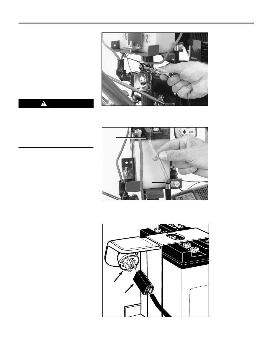
4. Check the tightness of the upper
mounting screw that secures the negative
cable and starter solenoid to the battery
post. See Figure 2-20. Scrape away any
paint between the cable and the screw as
the paint can prevent a good electrical
ground.
5. Install one end of the clear plastic vent
tube over the vent fitting (U, Figure 2-21)
on the battery. Insert the other end down
into the vent tube shield (V).
STEP 4: Connect Wiring Harness
Attach the wiring harness receptacle to
the prongs on the back of the ignition
switch (see Figure 2-22).
IMPORTANT: This completes the assem-
bly steps for the electric start tiller. Be
sure to read the rest of this Manual, and
the separate Engine Owner’s Manual,
before you operate your tiller.
12
Figure 2-20: Check tightness of upper mounting screw.
Figure 2-21: Install vent tube.
Figure 2-22: Attach wiring harness to keyswitch.
Keyswitch
Wiring Harness
U
V
Improper venting can cause a battery to
explode, resulting in severe personal
injury or property damage.
Be sure that the vent tube does not
become kinked, folded or pinched along
its entire length.
WARNING