MGE UPS Systems S3 User Manual
Page 31
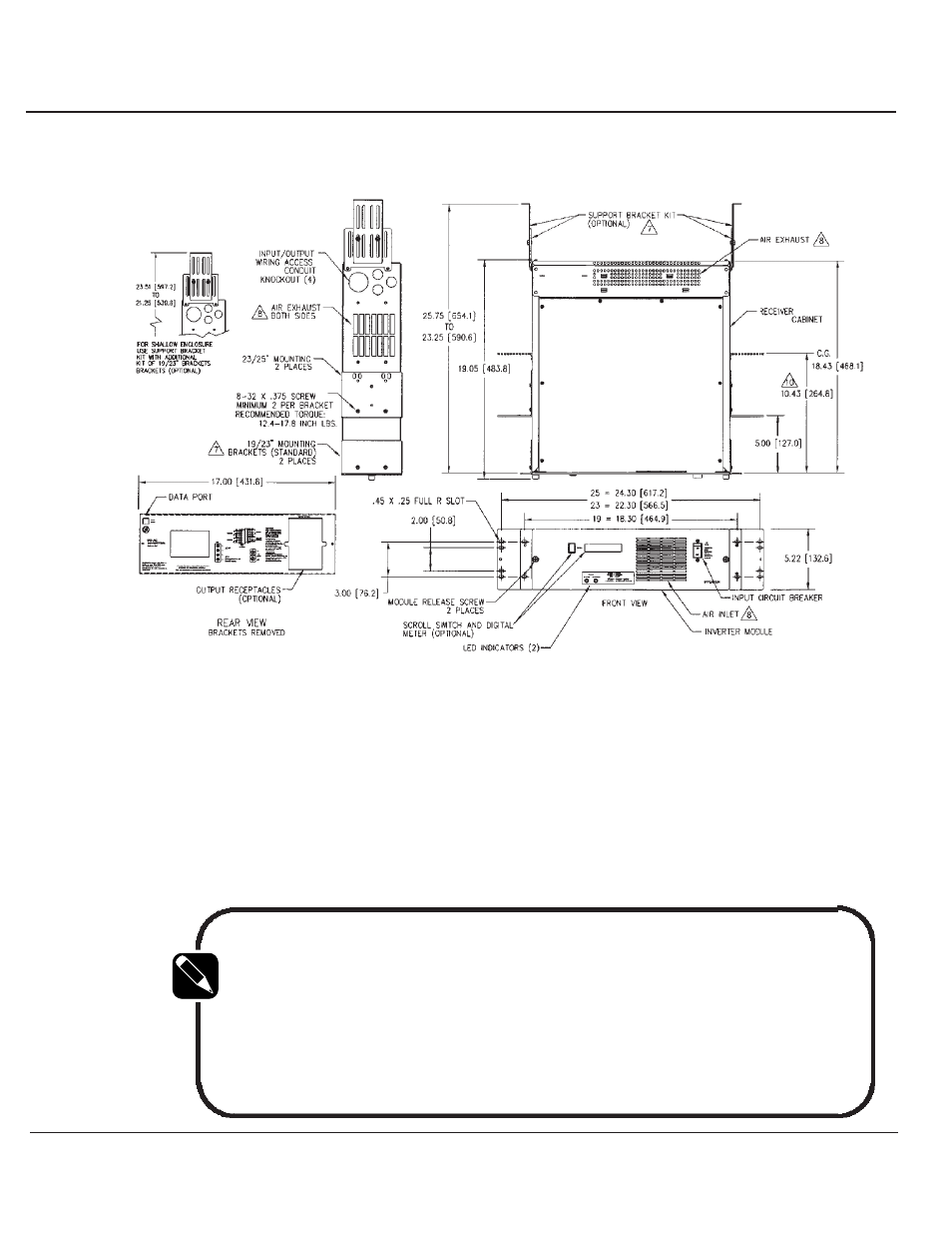
F i g u r e : O u t l i n e a n d M o u n t i n g fo r 2 k VA
2- 1B
The side mounting brackets can be positioned for either a 19
inch, 23 inch, or 25 inch rack.
The Inverter can also be
mounted either flush with the front panel or at the chassis
midpoint.
Prior to mounting the Inverter in the rack,
determine the position of all input and output wiring.
NOTE
Input and output conductors must be sized for the maximum current
as shown in Table 2-1 and otherwise be in compliance with applica-
ble electrical codes. Be sure all connections are fully tightened.
D.C. input terminals can accommodate wire size up to one "0" gauge
wire.
2.5.2
Mounting And
Wiring Access
86-153061-00
2 — 3
Installation and Operation
Owner’s Manual
See also other documents in the category MGE UPS Systems Tools:
- Pulsar EX 1000 (28 pages)
- 4.5 kVA (32 pages)
- 1100 (196 pages)
- EPS 8000 (54 pages)
- S EXB 2500 (22 pages)
- Pulsar Extreme 3200C (28 pages)
- ESV 22+Rack (24 pages)
- GES-801L (22 pages)
- Comet EX 7 RT 3:1 (38 pages)
- EX 11RT (72 pages)
- Galaxy PW (44 pages)
- 3 (34 pages)
- Pulsar TM 30 (18 pages)
- 22+ EB 22 (44 pages)
- 1500C (28 pages)
- Rackmount PDU (36 pages)
- Pulsar Esprit 313.5 kVA (6 pages)
- EX-5 (76 pages)
- 30A (30 pages)
- AmpMeter PDU (52 pages)
- EX30 (106 pages)
- 1100 Tower (36 pages)
- 40-75KVA (56 pages)
- 2000 (34 pages)
- 4000 RT (38 pages)
- Pulsar EXtreme C UPS 1500 VA (4 pages)
- FlexPDU 6 AUS (12 pages)
- POWER-SURE 700 (52 pages)
- 250A (34 pages)
- EX 1000 (28 pages)
- EX7 (18 pages)
- EX30Rack (24 pages)
- 12280 kVA (13 pages)
- 40-150kVA (56 pages)
- 100 (32 pages)
- Uninterruptible Power Provider (4 pages)
- EPS 7000 (62 pages)
- 300 (6 pages)
- EX10Rack (22 pages)
- 500 (4 pages)
- EPS 6000 (84 pages)
- EX RT CLA (6 pages)
- 3000 (32 pages)
- 3.5 to 21 kVA N+1 (54 pages)