Mvp210 circuit board, Ch1 ch2, Ch 2 jumper block – Multi-Tech Systems MULTIVOIP MVP210/410/810 User Manual
Page 12: Ch 1 jumper block
Chapter 2: Installing and Cabling the MultiVOIP
Multi-Tech
Systems,
Inc.
12
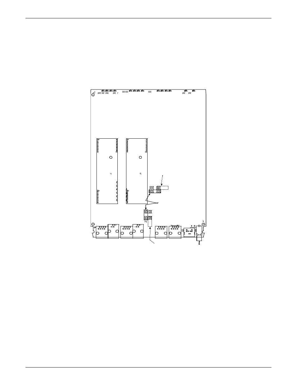
For DID channels only
For any channel on which you are using the DID interface type, you must change the jumper on the MultiVOIP
circuit card. DID is not supported on the –SS or –FX models.
1. Disconnect power. Unplug the AC power cord from the wall outlet or from the receptacle on the
MultiVOIP unit.
2. Using a #1 Phillips driver, remove the screw (at bottom of unit, near the back-cover end) that attaches the
main circuit card to the chassis of the MVP210.
3. Pull the main circuit card out about half way.
4. Identify the channels on which the DID interface will be used.
J3
J 7
J9
J5
J 11
F B 3
L E D 2
R7 2
J1
S 1 0
R 113
R114
L E D1 2
J 15
L E D 7
L E D11
L E D 10
L E D 1 4
LE D 5
LE D3
L E D1
R58
R2
R 57
L ED6
LE D 4
LE D9
R56
R 74
R2 05
L ED 1 3
R5 5
LE D 8
Ch1
Ch2
Ch 2 Jumper
Block
MVP210 Circuit Board
JP1
JP8
as configured
for DID Interface
as shipped,
for non-DID interfaces
Ch 1 Jumper
Block
JP7
JP4
as configured
for DID Interface
P7
Figure 2-4: MVP210 Channel Jumper Settings
5. Position the jumper for each DID channel so that it does not connect the two jumper posts. For DID
operation of a VOIP channel, the MultiVOIP will work properly if you simply remove the jumper altogether,
but that is inadvisable because the jumper might be needed later if a different telephony interface is used
for that VOIP channel.
6. Slide the main circuit card back into the MultiVOIP chassis and replace the screw at the bottom of the
unit.