Mounting the lm2000, Lm2000, Base mounting – Murphy Lube Level Maintainer LM2000 User Manual
Page 2: Caution
LM-00011N page 2 of 4
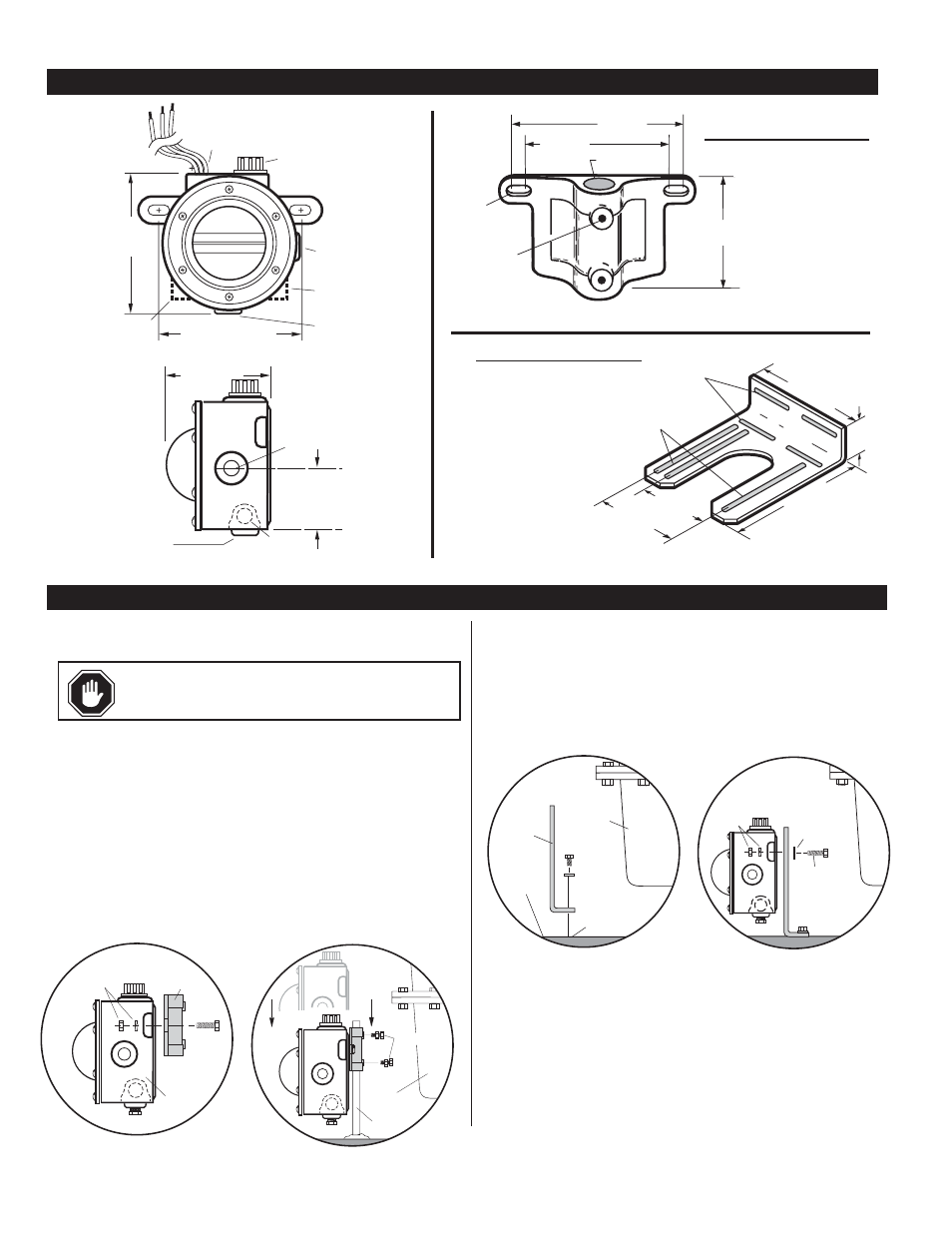
TYPICAL INSTALLATION
DIMENSIONS
1/2 in. Electrical
Female Conduit
Connection
Crankcase
Balance Vent
1/2 NPTF
4-5/8 in.
(117 mm)
4-1/2 to 5-3/16 in.
(114 to 132 mm)
Oil Inlet
Connection
1/2 NPTF
Oil Outlet
Connection
3/4 NPTF
3/8 NPTF
LM2000S
3/8 NPTF
LM2000S
2-7/8 in.
(73 mm)
CL
2-1/4 in.
(57 mm)
Oil Inlet
Connection
1/2 NPTF
Oil Outlet
Connection
3/4 NPTF
3/8 NPTF
LM2000S
LM2000
Mounting the LM2000
NOTE: Mount the LM2000 as close as possible to the crankcase.
The following instructions are based on the usage of the pipe and universal
mounting brackets shown above.
Pipe Bracket Mounting (15000238)
1. Mount a nominal 1/2 inch (13 mm) diameter pipe to the base of the engine.
2. Install the pipe bracket to the LM2000 using two 1/4-20 UNC x 1 inch
bolts, nuts and lock washers supplied. See Figure 1A.
3. Slip the LM2000 onto the pipe and install the two adjustment bolts. Each
bolt consists of a 1/4-20 UNC x 1 in. bolt, nuts and lock washers. See
Figure 1B. DO NOT tighten the adjustment screws too tightly because
you will have to adjust the LM2000 later in the installation process.
Mounting with Universal Bracket (15000370)
The universal bracket has two mounting methods: base mounting or
pan mounting.
Base Mounting
1. Install the universal bracket to the base as shown in Figure 2A using two
flat washers and two 5/16 inch dia. bolts or others as necessary.
2. Mount the LM2000 to the universal bracket using two 1/4-20 UNC x 1-
1/4 inch (32 mm) bolts, nuts and lock washers supplied (Figure 2B).
DO NOT tighten the adjustment screws too tightly. You will have to
adjust the LM2000 later in the installation process.
Figure 1B
LM2000
Pipe
Bracket
Lock Washer
and Nut
Bolt
Pipe
Crankcase
Adjustment
Bolts
Figure 1A
Figure 2B
Crankcase
Base
Universal
Bracket
Threaded
hole
Adjustment
Bolts
Flat
Washer
Lock Washer
and Nut
Figure 2A
1-3/4 in.
(44 mm)
7-1/2 in.
(191 mm)
Slot, 29/64 in. (14 mm)
x 4-3/8 in. (111 mm)
3 places
6-11/1
6 in.
(170 mm)
Slot, 29/64 in. (14 mm)
x 2-3/8 in. (60 mm)
4 places
4-1/2 in.
(114 mm)
5-3/16 in.
(132 mm)
4-1/2 in.
(114 mm)
5-3/16 in.
(132 mm)
2-1/2 in.
(63.5 mm)
Hole 7/8 in.
(22 mm) dia.
1/4-20 NC
2 places
9/32 x 5/8 in.
(7 x 16 mm)
2 places
15000238
Pipe Bracket Kit
15010224
Universal Flange Kit
Additional Hardware
Supplied
(2) 1/4-20 x 7/8 inch
(22 mm) screws
(2) 1/4-20 x 1 inch
(25 mm) screws
(4) 1/4-20 hex nuts
(4) 1/4 inch (6 mm) dia.
split washer
Additional Hardware
Supplied
(2) 1/4-20 x 1/4 inch
(32 mm) bolts
(4) 1/4 inch dia. flat washer
(2) 1/4-20 hex nuts
(2) 5/16-18 x 1/4 inch
(32 mm) bolts
(4) 5/16 dia. flat washer
(2) 5/16-18 hex nuts
CAUTION:
Excessive vibration can cause over-
fill. Be sure mounting brackets are supported.