Attaching clutch grips, Attaching handle panel, Attaching speed selector plate and shift lever – MTD 611 User Manual
Page 8: Attaching control cables
8
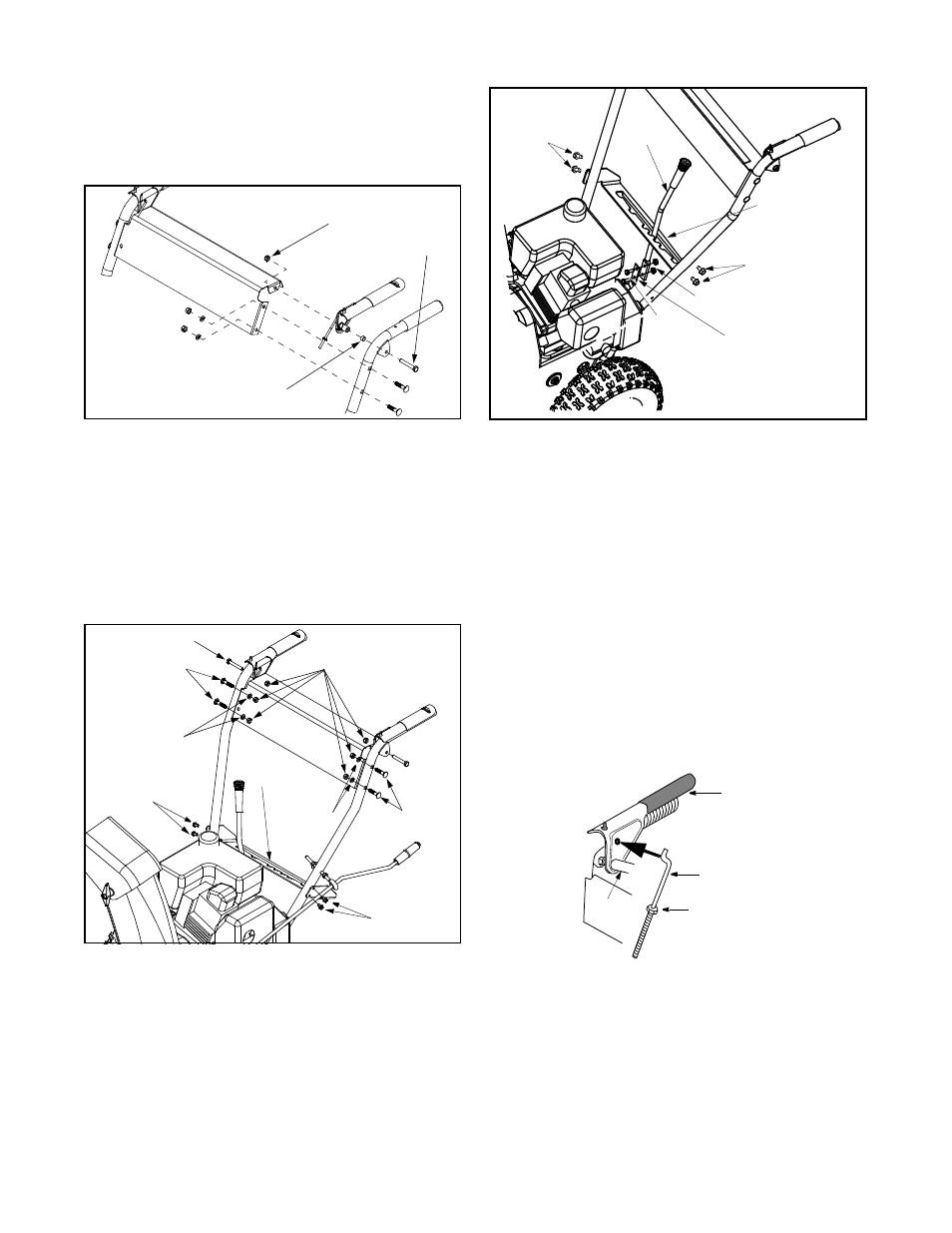
Attaching Clutch Grips
(Hardware Group B)
•
Slide spacer on each end of the clutch grip and
place the clutch grip in position on the each
respective handle. Clutch grips must sit on top of
the handles. See Figure 6.
Figure 6
•
Secure each clutch grip with a hex bolt threaded
from the outside of each handle and tighten with
hex lock nut under handle panel. See Figure 6.
Attaching Handle Panel
(Hardware Group C)
•
Position the handle panel between handles and
insert two carriage bolts on each side and secure
with lock washers and hex patch nuts.
See Figure 7.
Figure 7
Attaching Speed Selector Plate And
Shift Lever
(Hardware Group D)
•
Assemble the speed selector plate to the outside
of the handles. Secure using two self-tapping
screws on each side. See Figure 8.
•
Insert the shift lever through slot in the speed
selector plate. See Figure 8.
Figure 8
NOTE: The bend in the lever should be towards the
operator.
•
Secure shift lever to the shift lever spring using two
hex bolts and hex lock nuts. Tighten both bolts
finger tight. At this point the shift lever and shift
lever spring are not against each other. As you
tighten the bolts and nuts with two wrenches, these
will pull together.
•
Tighten all hardware assembled to this point. Make
sure that clutch grips are moving freely.
Attaching Control Cables
(Hardware Group E)
•
Take a “Z” fitting from the hardware pack and insert
the Z end into the hole on the left clutch grip on the
handle panel. See Figure 9. Thread a hex nut from
hardware pack on to the Z fitting.
Figure 9
•
Route the left cable between engine and speed
selector plate and then between handle panel and
clutch lever pivot rod. Make sure the cable is routed
correctly in the cable roller guides located at the
lower rear of the unit.
•
Thread cable onto the left “Z” fitting.
•
Assemble the right “Z” fitting on the right clutch grip
and attach the right cable in the same manner. Both
Spacer
Hex Bolt
Hex Lock Nut
Carriage Bolts
Self-Tapping
Screws
Self-Tapping
Screws
Hex Lock Nuts
Lock Washer
Lock
Washer
Carriage
Bolts
Speed
Selector
Plate
Hex Cap Screw
Self-Tapping
Screws
Self-Tapping
Screws
Hex Lock Nuts
Hex
Bolts
Shift Lever
Spring
Speed Selector
Plate
Shift Lever
Self-Tapping
Screws
Self-Tapping
Screws
“Z” Fitting
Hex Nut
Clutch Grip
Handle
Panel