Chute assembly, Auger control, Skid shoes – MTD 611 User Manual
Page 15: Carburetor, Drive wheels
15
Chute Assembly
The distance snow is thrown can be adjusted by
changing the angle of the chute assembly. To do so,
stop the engine by removing the ignition key and loosen
the plastic wing knobs found on either side of the
discharge chute. Pivot the chute upward or downward
before re-tightening the wing knobs.
Auger Control
Refer to Auger Control Test in the Operating Section to
adjust the auger control.
Skid Shoes
The space between the shave plate and the ground can
be adjusted. See Figure 19.
•
For close snow removal on a smooth surface, raise
skid shoes higher on the auger housing.
•
Use a middle or lower position when the area to be
cleared is uneven.
Figure 19
WARNING:
Do not operate this snow
thrower on gravel as loose gravel can be
easily picked up and thrown by the auger
causing injury to the operator and/or damage
to the snow thrower.
•
Adjust skid shoes by loosening the four hex nuts
and carriage bolts. Move skid shoes to desired
position.
•
Make certain the entire bottom surface of skid shoe
is against the ground to avoid uneven wear on the
skid shoes. Retighten nuts and bolts securely.
Carburetor
•
Minor carburetor adjustment may be required to
compensate for differences in fuel, temperature,
altitude and load.
•
Refer to the separate engine manual, packed with
your unit, for carburetor adjustment information.
WARNING:
If any adjustments need to be
made to the engine while the engine is
running (e.g. carburetor), keep clear of all
moving parts. Be careful of muffler, engine
and other surrounding heated surfaces.
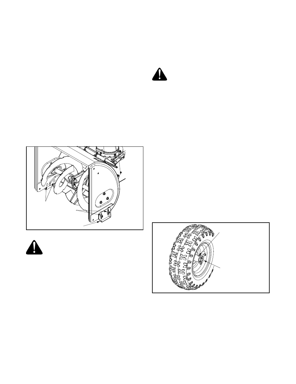
Drive Wheels
The wheels may be adjusted for two different methods
of operation. The adjustment is made by placing the
click pins in one of two different holes on the right side
of the unit. See Figure 20.
One Wheel Driving: Insert the click pin only through
the outside hole of the axle (NOT the rim) on the right
side of the snow thrower. This position gives power
drive to the left wheel only, making the unit easier to
maneuver.
Both Wheels Driving: Insert the click pin through the
hole in the hub of the rim and the INSIDE hole on the
snow thrower’s right axle. This position is good for
heavy snow as there is power drive in both wheels.
IMPORTANT:
NEVER operate the snow thrower with
the click pin inserted through both the RIM and the
OUTSIDE HOLE in the axle. Doing so can result in
serious damage to the drive system.
Figure 20
Skid
Shoes
Carriage
Bolts
Hex Nuts
Inside Hole
In Axle
Click Pin In
Outside Hole