Assembly, Installing the handle, Adjusting the wheel guard – Grizzly 4" User Manual
Page 9
t10493, t10494 & t10495 (Mfg since 10/11)
-7
-
assembly
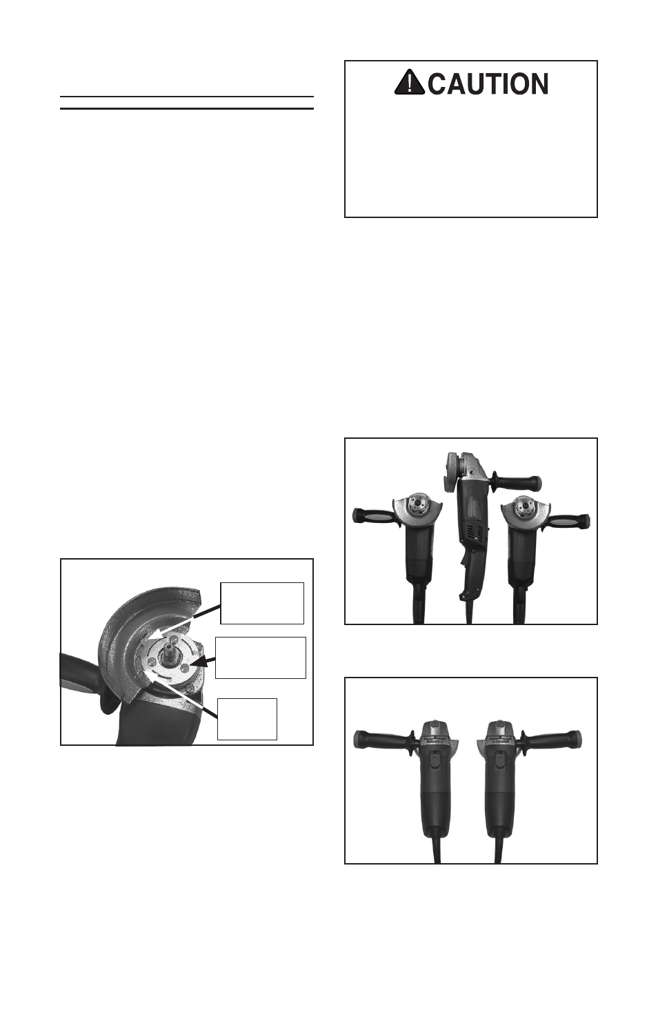
figure 5. three handle configurations for
t10494/t10495.
figure 6. two handle configurations for
the t10493.
installing the handle
these angle grinders include a handle
and mounting holes for different handle
configurations, as shown in
figures
5–6. the handle provides added stability
while operating the grinder. Choose the
configuration that provides the most safe
and stable grinder control for each task,
and thread the handle into the appropriate
hole.
always consider the position of the
wheel guard when installing the
handle. never operate the grinder
with the handle installed toward the
open face of the guard. this could
lead to injury.
adjusting the Wheel guard
the wheel guards can be adjusted
for maximum safety during grinding
operations.
to adjust the guard:
1. remove the wheel and both flanges.
2. loosen the three phillips head screws
in the guard plate.
3. rotate wheel guard to the desired
position and retighten the screws loos-
ened in
step 2.
Note: The mounting hardware for
Model T10493 and Models T10494
and T10495 are different. For Model
T10493, ensure that the guard plate
clip is seated in one of the five posi-
tion holes on the wheel guard, as
shown in
Figure 4.
figure 4. adjusting the t10493 wheel
guard.
position
holes
guard plate
Clip
phillips head
screw
4. re-install the wheel and flanges (refer
to
installing/changing grinding
Wheels on page 16).